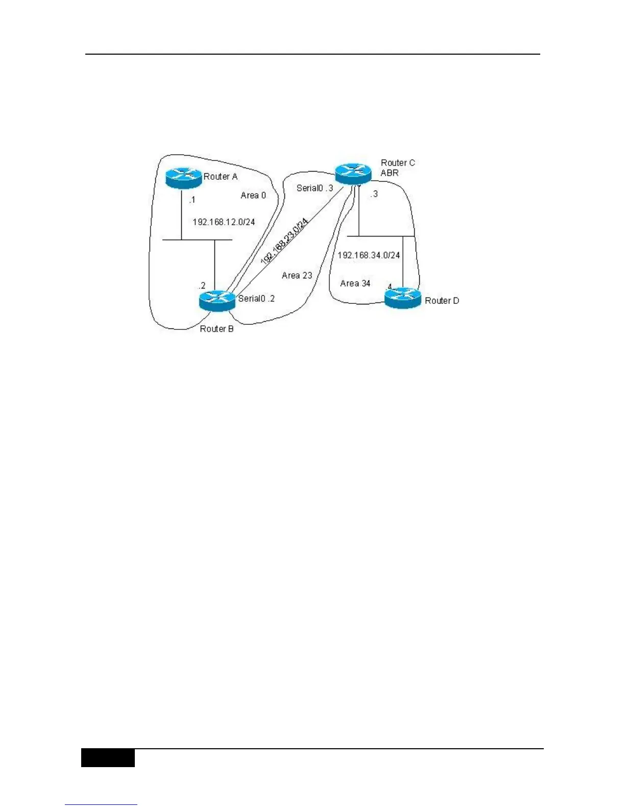
Four devices form an OSPF routing area. Networks 192.168.12.0/24 belongs to area 0,
network 192.168.23.0/24 to area 23, while network 192.168.34.0/24 belongs to area 34.
Figure 28-7 shows the IP address allocation and connection of the device.
Figure 28-7 Example of configuring OSPF virtual connection
The purpose is to allow device D to learn the routes of 192.168.12.0/24 and
192.168.23.0/24.
Concrete Configuration of Devices
The OSPF routing area consists of multiple sub-areas, each of which must be connected to
the backbone area (area 0) directly. If there is no direct connection, a virtual link must be
created to ensure logical connection to the backbone area. Otherwise, the sub-areas are not
in connection. The virtual connection must be configured on the ABR.
The configuration of device A:
#Configuring Ethernet interface
interface FastEthernet0/0
ip address 192.168.12.1 255.255.255.0
#Configure the OSPF routing protocol
router ospf 1
network 192.168.12.0 0.0.0.255 area 0
The configuration of device B:
#Configuring Ethernet interface
interface FastEthernet0/0
ip address 192.168.12.2 255.255.255.0
#Configure the WAN port
interface Serial1/0
ip address 192.168.23.2 255.255.255.0