to this port is of the same MST Region as itself. Otherwise, it is considered to come from
another Region.
We recommend you configure the corresponding table of the Instance-Vlan in the
STP-closed mode, and then enable the MSTP to ensure the stability and convergence of the
network topology.
17.1.2.3 Spanning Tree within MSTP region (IST)
After the MSTP Region is partitioned, each Region will select separate root bridge of various
instances and the port role of various ports for each device according to such parameters as
the bridge priority and port priority. Finally, it will specify whether this port is FORWARDING
or DISCARDING within this instance for the Port Role.
In this way, the IST (Internal Spanning Tree) is generated by the communication of the MSTP
BPDU, and various Instances present separate spanning tree (MSTI). Where, the spanning
tree corresponding to the Instance 0 is referred to as the CIST (Common Instance Spanning
Tree). That is to say, each Instance provides each vlan group with a single network topology
without loop.
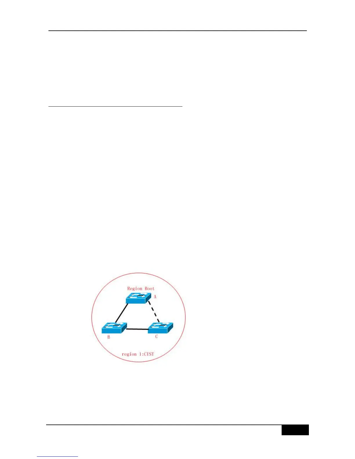
As is shown in Figure below, the devices A, B and C form the loop within the region 1.
As is shown in Figure 17-17, device A with the highest priority is selected as the Region Root
in the CIST (Instance 0). Then, the path between devices A and C are DISCARDING
according to other parameters. Hence, for the vlan group of the Instance 0, only the path
from switch A to B and device B to C is available, which breaks the loop of the vlan group.
Figure 17-17
As is shown in Figure 17-18, switch B with the highest priority is selected as the Region Root
in the MSTI 1 (Instance 1). Then, the link between switch B and C is DISCARDING
according to other parameters. Hence, for the ―Vlan group‖ of the instance 1, only the path
from switch A to B and switch A to C is available, which breaks the loop of the ―Vlan group‖.