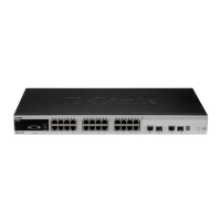
Figure 17-18
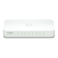
As is shown in Figure 17-19, switch C with the highest priority is selected as the Region Root
in the MSTI 2 (Instance 2). Then, the link between switch A and B is DISCARDING
according to other parameters. Hence, for the ―Vlan group‖ of the instance 2, only the path
from switch B to C and switch A to C is available, which breaks the loop of the ―Vlan group‖.
Figure 17-19
It‘s noted that the MSTP protocol doesn‘t concern with which Vlan the port is of, so users
should configure corresponding Path cost and Priority for related port according to actual
vlan configuration, to prevent the MSTP protocol from breaking the loop unexpected.
17.1.2.4 Spanning Tree between MSTP regions
(CST)
For CST, each MSTP region is equivalent to a whole large-sized device, and different MSTP
Regions also span a large-sized network topology tree, referred to as the CST (common
spanning tree). As shown in Figure 17-20, for CST, device A with the smallest Bridge ID is
selected as the root of the entire CST (CST Root) and the CIST Regional Root in this Region.