AKD BASIC User Guide | 6 AKD BASIC Parameters, Operators, Statements
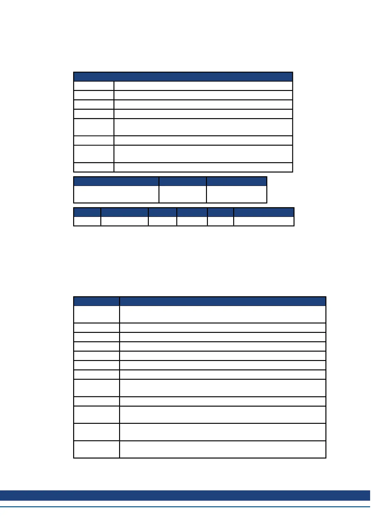
6.11.14 DRV.EMUEMODE
General Information
Type R/W Parameter
Description Sets the mode of the emulated encoder output (EEO) connector.
Units N/A
Range 0 to 11
Default
Value
0
Data Type Integer
See Also
DRV.EMUERES , DRV.EMUEZOFFSET , DRV.EMUE-
MTURN
Start Version M_01-00-00-000
Fieldbus Index/Subindex Object Start Version
EtherCAT COE and CAN-
open
3534h/0 M_01-00-00-000
Fieldbus Index/Subindex Is 64 bit? Attributes Signed? Object Start Version
Modbus 246 No 16 bit No M_01-03-00-000
Description
When the emulated encoder output (EEO) is configured to generate an absolute index pulse
(DRV.EMUEMODE is 2, 7 or 9) this parameter and DRV.EMUEZOFFSET define the location
of the Z pulse. DRV.EMUEMTURN is used to define which turn of the position range the Z
pulse is located. DRV.EMUEZOFFSET is used to define the position of the Z pulse within one
revolution.
This parameter sets the EEO connector to act as either an input or output as follows.
Setting Function
0 (rec-
ommended)
Input (see FB2.MODE to select the type of inputs the secondary feedback
will accept)
1 EEOOutput, A/B with once per rev index
2 EEOOutput, A/B with absolute index pulse.
3 Input, A/B signals (Deprecated)
4 Input, step and direction signals (Deprecated)
5 Input, CW/CCW (Up/Down) Signals (Deprecated)
6 Step/Dir with one Z-pulse/rev
7
Step/Dir with one absolute Z-pulse (depends on DRV.EMUEOFFSET and
DRV.EMUETURN)
8 CW/CCW output with one Z-pulse/rev
9
CW/CCWoutput with one absoulte Z-pulse (depends on DRV.EMUEOF-
FSET and DRV.EMUETURN)
10
Allows the X9 connector to be used as a General Purpose I/O or SynqNet
fieldbus controlled I/O (See DIO9.DIR to DIO11.DIR )
11
FB3 Input (Tertiary feedback is reported with FB3.P). Use FB3.MODE to
select the feedback type.
Modes 3 to 5 are backwards compatible but deprecated. Refer to FB2.MODE and
FB2.SOURCE instead.
Kollmorgen™ | March 30, 2012 230