9 Arc Welding Application
9.12 Power Source Condition File
9-87
149235-1CD
RE-CSO-A031
< Example >
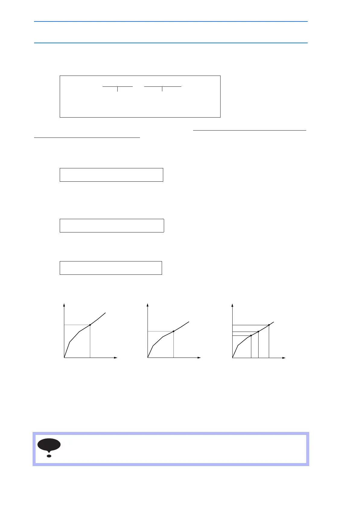
An example is shown with the ARCON instruction.
If the welding current output is 250A, the welding voltage can be specified as follows:
With the voltage characteristics with the following Figure A, the above instruction causes the output of
7.5V control signal to the Power Source
If the welding current output value is changed to 220A, a minor correction to the ARCON instruction
causes the output of the control signal associated with 100% of the proper output value at 220A. (Fig.B)
Also note that a minor adjustment of the welding voltage can be instructed easily. (Fig.C)
e.g. The control signal is output 110% of the proper output value at 220A.
or
e.g. The control signal is output 94% of the proper output value at 220A.
This setting method enables easy adjustment without calculating the voltage output.
This method can be also applied to condition data files and instructions other than ARCON. Another
advantage is that a single welding job can be used with more than one Power Source with a synergic
power supply by changing the welder condition data file.
ARCON AC=250
Welding
current
250A
AVP=100
100% of proper output,
assuming the use of
synergic power supply.
ARCON AC=220 AVP=100 100% output
ARCON AC=220 AVP=110 110% output
ARCON AC=220 AVP=94 94% output
If welding current output is significantly different from the voltage characteristics
measurement used, voltage output may vary. Write the welding current value used for the
voltage characteristics measurement as a comment for reference.
0 7.5
(V)
(%)
100
94
110
0 7.5
Welding voltage reference value
Figure A
(V)
(%)
100
Voltage characteristics
at 250A
0 7.5
(V)
(%)
100
Welding voltage
output value
Welding voltage
output value
Welding voltage
output value
Voltage characteristics
at 220A
Welding voltage reference value
Figure B
Welding voltage reference value
Figure C

 Loading...


