2 Manipulator Coordinate Systems and Operations
2.1 Control Groups and Coordinate Systems
2-2
149235-1CD
RE-CSO-A031
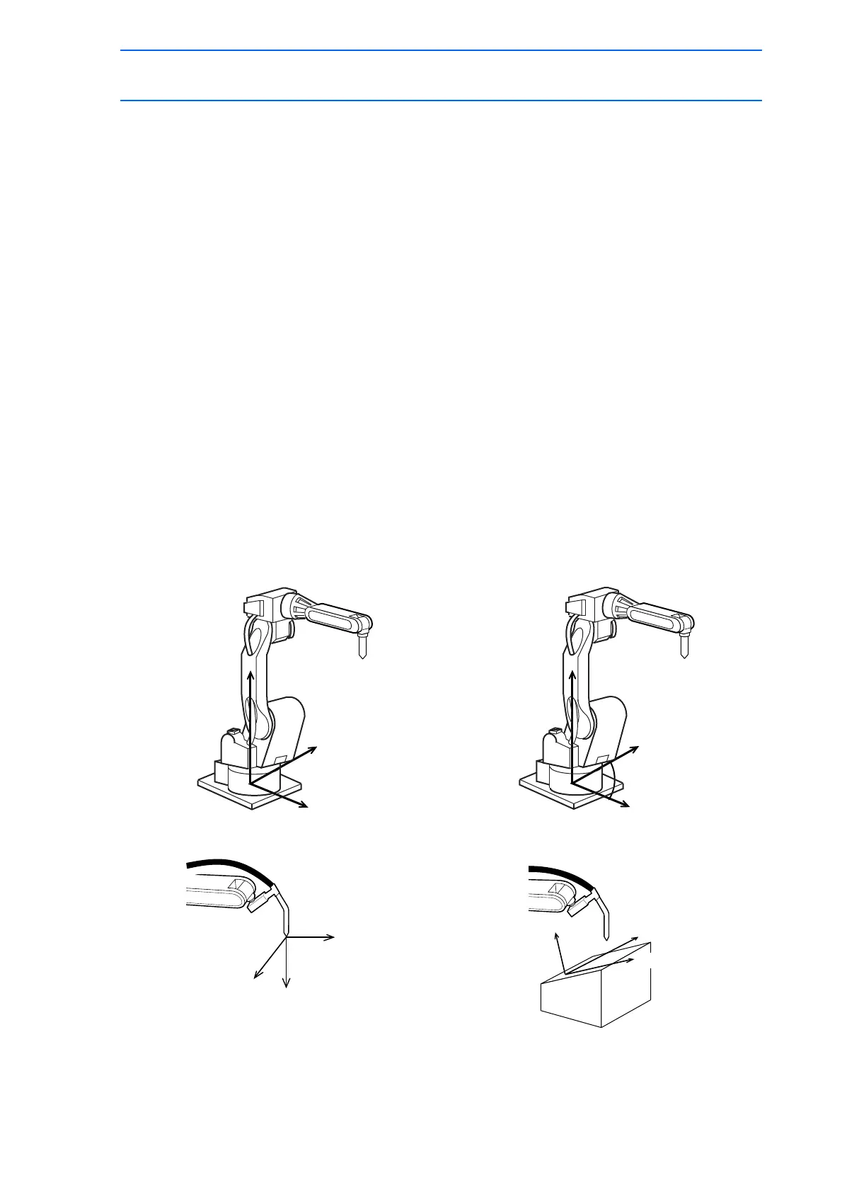
2.1.2 Types of Coordinate Systems
The following coordinate systems can be used to operate the manipulator:
• Joint Coordinates
Each axis of the manipulator moves independently.
• Cartesian Coordinates
The tool tip of the manipulator moves parallel to any of the X-, Y-, and Z-axes.
• Cylindrical Coordinates
The θ axis moves around the S-axis. The R-axis moves parallel to the L-axis arm. For
vertical motion, the tool tip of the manipulator moves parallel to the Z-axis.
• Tool Coordinates
The effective direction of the tool mounted in the wrist flange of the manipulator is defined
as the Z-axis. This axis controls the coordinates of the end point of the tool.
• User Coordinates
The XYZ-cartesian coordinates are defined at any point and angle.
The tool tip of the manipulator moves parallel to the axes of them.
Cartesian Coordinates Cylindrical Coordinates
Tool Coordinates User Coordinates
Z-axis
θ -axis
r-axis
r-axis

 Loading...


