AKD BASIC User Guide | 6 AKD BASIC Parameters, Operators, Statements
This parameter sets the functionality of the digital inputs 1 through 7. Digital inputs and cor-
responding X7 and X8 pin connectors are described in the AKD Installation Manual, section
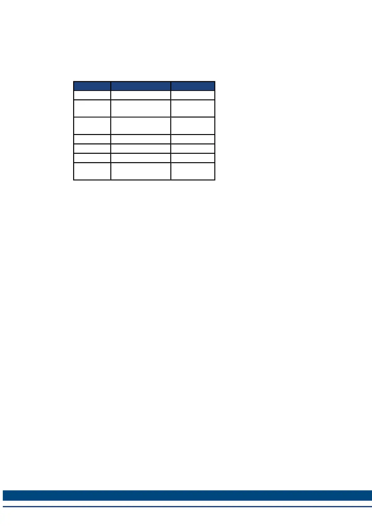
8.16.4, Digital Inputs. The table below summarizes the digital input modes; for detailed descrip-
tions of each mode, see 1 Digital Inputs and Outputs.
DINx.MODE Description Task
0 No function; off 0 - None
1 Fault reset
1 - Back-
ground
7 Reserved
7 - Back-
ground
12 Reserved 12 - None
14 Reserved 14 - None
18 Positive limit switch 18 - 4 kHz
19
Negative limit
switch
19 - 4kHz
199 Kollmorgen™ | March 30, 2012