AKD BASIC User Guide | 4 Quick Reference: Parameters, Functions, Operators
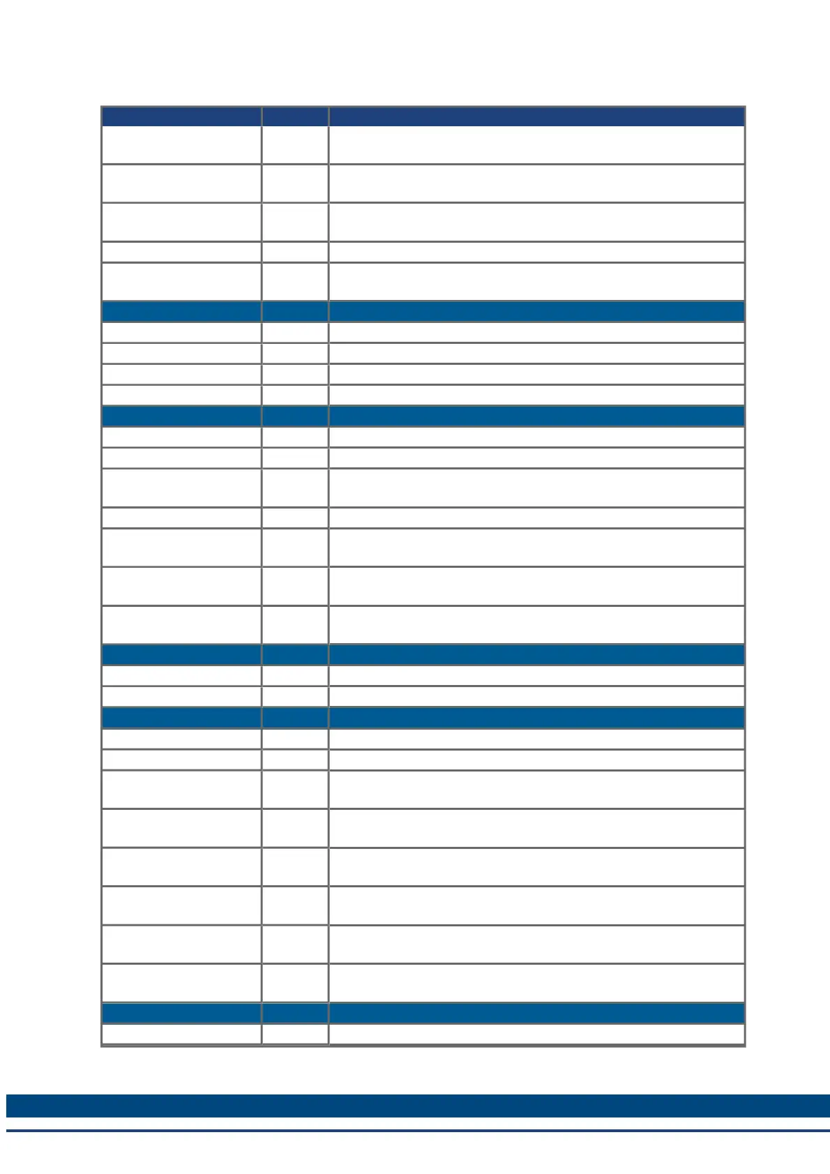
Parameter or Command Type Description
CAP0.PREFILTER,
CAP1.PREFILTER
NV Sets the filter for the precondition input source.
CAP0.PRESELECT,
CAP1.PRESELECT
NV Sets the precondition trigger.
CAP0.STATE,
CAP1.STATE
R/O Indicates whether or not trigger source was captured.
CAP0.T, CAP1.T R/O Reads time capture (if time capture was configured).
CAP0.TRIGGER,
CAP1.TRIGGER
NV Specifies the trigger source for the position capture.
Controlled Stop (CS)
CS.DEC NV Sets the deceleration value for the controlled stop process.
CS.STATE NV Returns the internal status of the controlled stop process.
CS.TO NV Sets the time value for the drive velocity to be within CS.VTHRESH .
CS.VTHRESH NV Sets the velocity threshold for the controlled stop.
Digital Input (DIN)
DIN.ROTARY R/O Reads the rotary knob value.
DIN.STATES R/O Reads the digital input states.
DIN1.FILTER TO
DIN7.FILTER
R/W Filter mode for digital inputs 1 to 7.
DIO9.INV to DIO11.INV R/W DIO9.INV to DIO11.INV
DIN1.MODE to
DIN19.MODE
NV Sets the digital input modes.
DIN1.STATE TO
DIN7.STATE
R/O Reads a specific digital input state.
DIN9.STATE to
DIN11.STATE
NV Shows on selected pin if signal is high or low.
DIO
DIO9.INV to DIO11.INV NV Inverting the output voltage of the IO, when in the output direction.
DIO9.DIR to DIO11.DIR NV Changing direction of the IOs from the X9 connector.
Digital Output (DOUT)
DOUT.RELAYMODE R/W Indicates faults relay mode.
DOUT.STATES R/O Reads the state of the two digital outputs.
DOUT8.MODE to
DOUT11.MODE
NV Sets the digital output mode.
DOUT1.PARAM AND
DOUT2.PARAM
NV Sets extra parameters for the digital outputs.
DOUT1.STATE AND
DOUT2.STATE
R/O Reads the digital output state.
DOUT1.STATEU AND
DOUT2.STATEU
R/W Sets the state of the digital output node.
DOUT9.STATE to
DOUT11.STATE
NV Shows on selected pin if signal is high or low.
DOUT9.STATEU to
DOUT11.STATEU
NV Allows user to set level of selected pin to high or low.
Drive (DRV)
DRV.ACC NV Describes the acceleration ramp for the velocity loop.
49 Kollmorgen™ | March 30, 2012