EasyManuals Logo

Toshiba e-STUDIO4500c Service Manual

Toshiba e-STUDIO4500c
1120 pages
To Next Page IconTo Next Page
To Previous Page IconTo Previous Page
Page #295 background imageLoading...
Page #295 background image
DUPLEX UNIT August, 2006
3-108
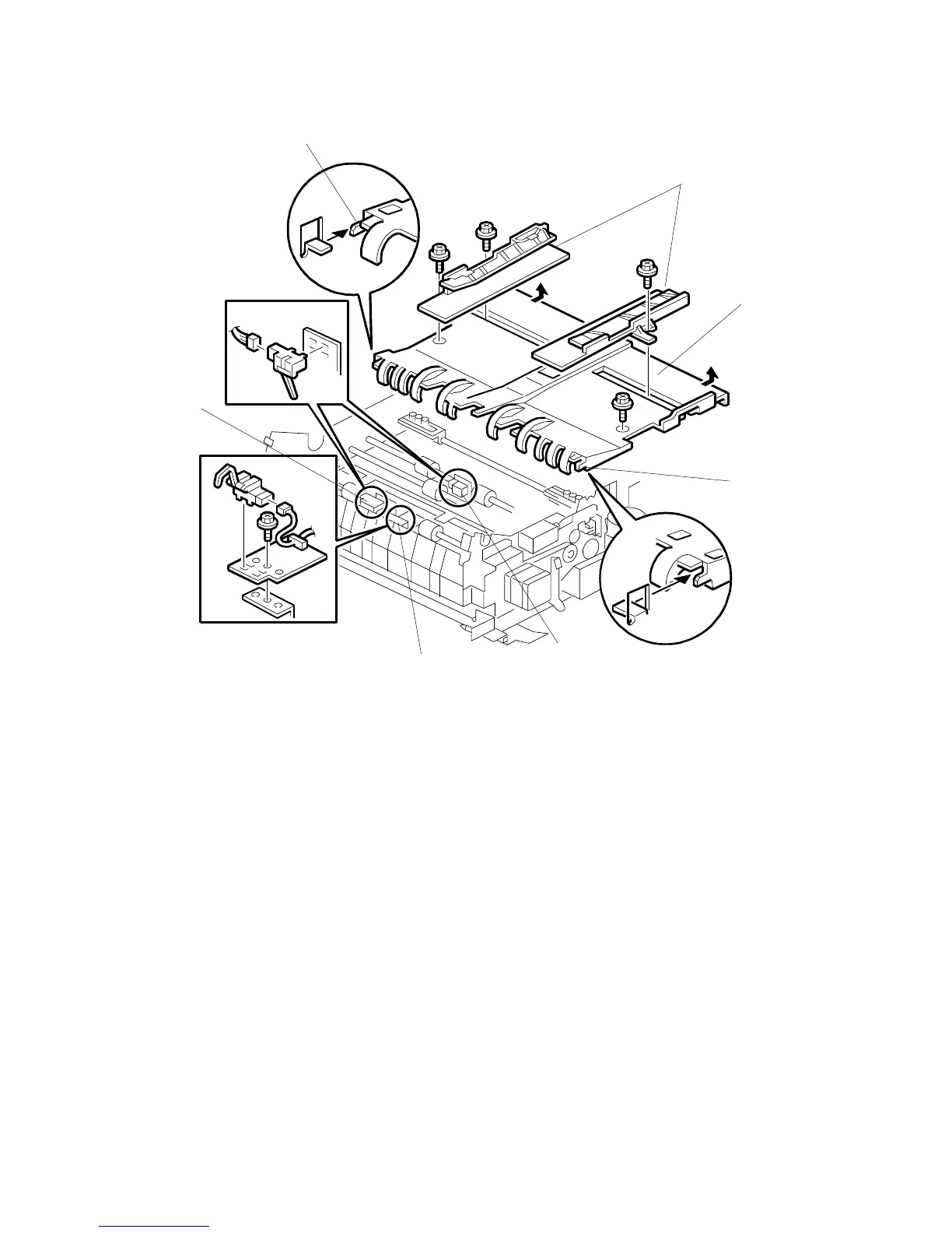
[A]: Jogger fences ( x 1 ea.)
[B]: Left transport cover ( x 2)
The front screw is a shoulder screw. Insert the screws in the correct holes
when re-attaching.
To avoid breaking the tabs under the left edge of the table, pull the table to
the right to disengage the tabs and then remove.
[C]: Transport sensor 1 (x 1, x 1)
[D]: Transport sensor 2 (x 1, x 1)
[E]: Inverter exit sensor ( x 1, x 1, x 1)
Reinstallation
Make sure the end tabs [F] of the left transport cover are engaged correctly.
B132R507.WMF
[A]
[B]
[C]
[D]
[E]
[F]
[F]

Table of Contents

Other manuals for Toshiba e-STUDIO4500c

Questions and Answers:

Question and Answer IconNeed help?

Do you have a question about the Toshiba e-STUDIO4500c and is the answer not in the manual?

Toshiba e-STUDIO4500c Specifications

General IconGeneral
BrandToshiba
Modele-STUDIO4500c
CategoryAll in One Printer
LanguageEnglish

Related product manuals