EasyManuals Logo

Toshiba e-STUDIO4500c Service Manual

Toshiba e-STUDIO4500c
1120 pages
To Next Page IconTo Next Page
To Previous Page IconTo Previous Page
Page #792 background imageLoading...
Page #792 background image
PROCESS CONTROL August 2006
6-76
6.11.2 COMPONENTS USED DURING PROCESS CONTROL
Potential Sensor
There is a potential sensor in each PCU above the surface of the drum.
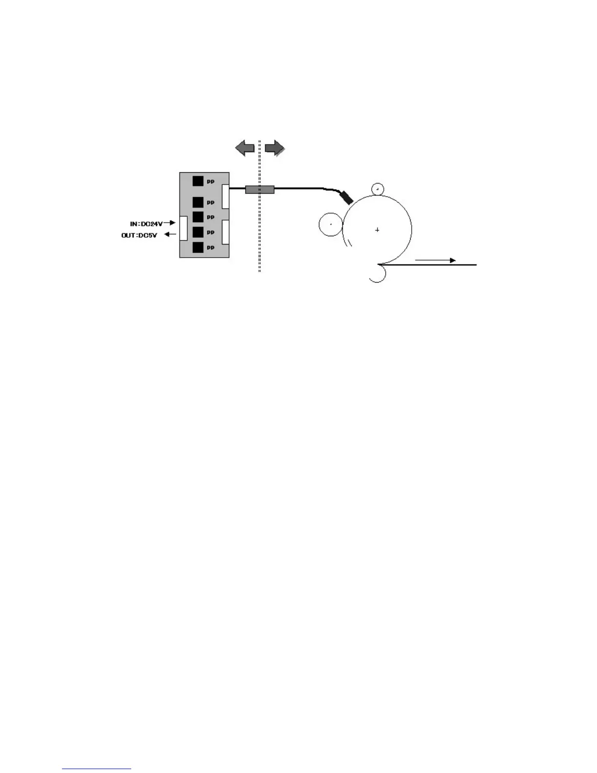
Each potential sensor consists of a probe and small power pack. A drawer
connector connects the probe and the power pack as shown above.
The potential sensor measures the potential of the drum immediately after it is
charged by the charge roller. It also measures a series of patterns (undeveloped
latent images) exposed on the drum by the laser diodes:
A detector in the center of a very small window measures the strength of the
electrostatic charge on the drum surface. The strengths of the charges vary,
depending on the surface potential of the drum.
A feedback circuit applies voltage to the probe until the strength of this charge
equals (offsets) the strength of the charge on the drum.
B132D901.WMF
Copier PCU
Potential
Sensor Probe
Drum Surface Potential
-900V (Max.)
Transfer Roller
1.5 kV (Normal Use)
5 kV (Transfer)
Development Roller
Range: -350 to -800 V DC
def. = -500V
Poten
tial Sensor PP
Max. Output: -1000V
Charge Roller
Drawer
Connector

Table of Contents

Other manuals for Toshiba e-STUDIO4500c

Questions and Answers:

Question and Answer IconNeed help?

Do you have a question about the Toshiba e-STUDIO4500c and is the answer not in the manual?

Toshiba e-STUDIO4500c Specifications

General IconGeneral
BrandToshiba
Modele-STUDIO4500c
CategoryAll in One Printer
LanguageEnglish

Related product manuals