Inter-Integrated Circuit Bus Controller Module (I
2
C)
PXN20 Microcontroller Reference Manual, Rev. 1
Freescale Semiconductor 32-21
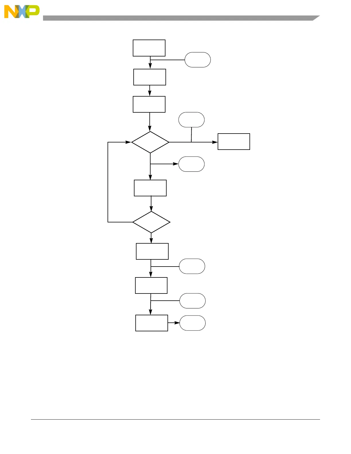
Figure 32-14. Flowchart of DMA Mode Master Transmit
32.5.2.2 DMA Mode, Master RX
Figure 32-15 details the exact operation for using a DMA controller to receive n data bytes from a slave.
The first byte (the slave calling address) is always transmitted by the CPU. All subsequent data bytes (apart
from the two last data bytes) can be read by the DMA controller. The last two data bytes must be
transferred by the CPU.
Config I
2
C for
Master TX
CPU writes calling
address to slave
interrupt
generated
Arb Lost or
No ack?
CPU handles
condition
yes
no
CPU sets
DMAENABLE
DMA writes 1
ipd_rx_req
generated
DMA written
data?
(n-1) bytes of
no
yes
CPU clears
DMA enable
interrupt
generated
Start
Generated
byte of data
CPU writes last
data byte
interrupt
generated
CPU clears
MS bit in CR
Stop
generated
 Loading...
