Deserial – Serial Peripheral Interface (DSPI)
PXN20 Microcontroller Reference Manual, Rev. 1
Freescale Semiconductor 30-43
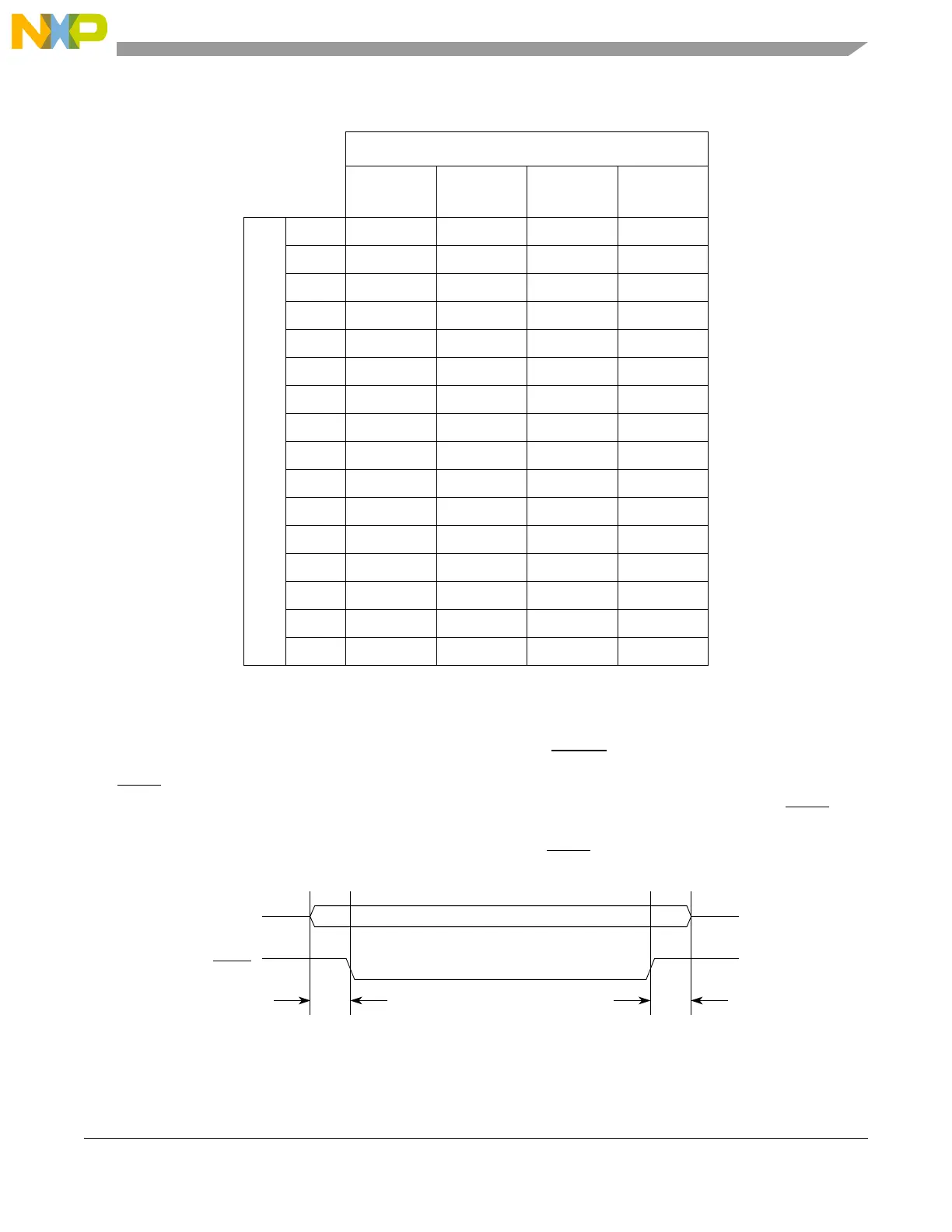
30.4.7.5 Peripheral Chip Select Strobe Enable (PCSS)
The PCSS signal provides a delay to allow the PCS signals to settle after a transition occurs, thereby
avoiding glitches. When the DSPI is in master mode and PCSSE bit is set in the DSPI_MCR, PCSS
provides a signal for an external demultiplexer to decode the PCS[0:4] signals into as many as 32
glitch-free PCS signals. Figure 30-28 shows the timing of the PCSS
signal relative to PCS signals.
Figure 30-28. Peripheral Chip Select Strobe Timing
Table 30-30. Delay after Transfer Computation Example in TSB Configuration
PDT field
Tdt
1
(Tsck)
1
Some values are not reachable (e.g., 9, 11, 13, 15, 17, 18, 19...), to
calculate these values, please see the Equation 30-3.
0123
DT field
0
2
2
The values in this row were rounded to the next integer value.
1234
11357
2 2 61014
3 4 12 20 28
4 8 24 40 56
5 164880112
6 32 96 160 224
7 64 192 320 448
8 128 384 640 896
9 256 768 1280 1792
10 512 1536 2560 3584
11 1024 3072 5120 7168
12 2048 6144 10240 14336
13 4096 12288 20480 28672
14 8192 24576 40960 57344
15 16384 49152 81920 114688
 Loading...
