AMBA Crossbar Switch (AXBS)
PXN20 Microcontroller Reference Manual, Rev. 1
Freescale Semiconductor 16-3
• Six slave ports
— Flash port dedicated to Z6 core
— Flash port for all other masters (refer to Chapter 12, Flash Memory Array and Control, for
information on accessing flash memory)
— 512K SRAM at address 0x4000_0000
— 80K SRAM at address 0x4008_0000
— AIPS A
— AIPS B
• 32-bit address, 64-bit data paths
• Fully concurrent transfers between independent master and slave ports
16.1.5 Modes of Operation
16.1.5.1 Normal Mode
In normal mode, the AXBS provides the register interface and logic that controls crossbar switch
configuration.
16.1.5.2 Debug Mode
The AXBS operation in debug mode is identical to operation in normal mode.
16.2 Memory Map and Register Definition
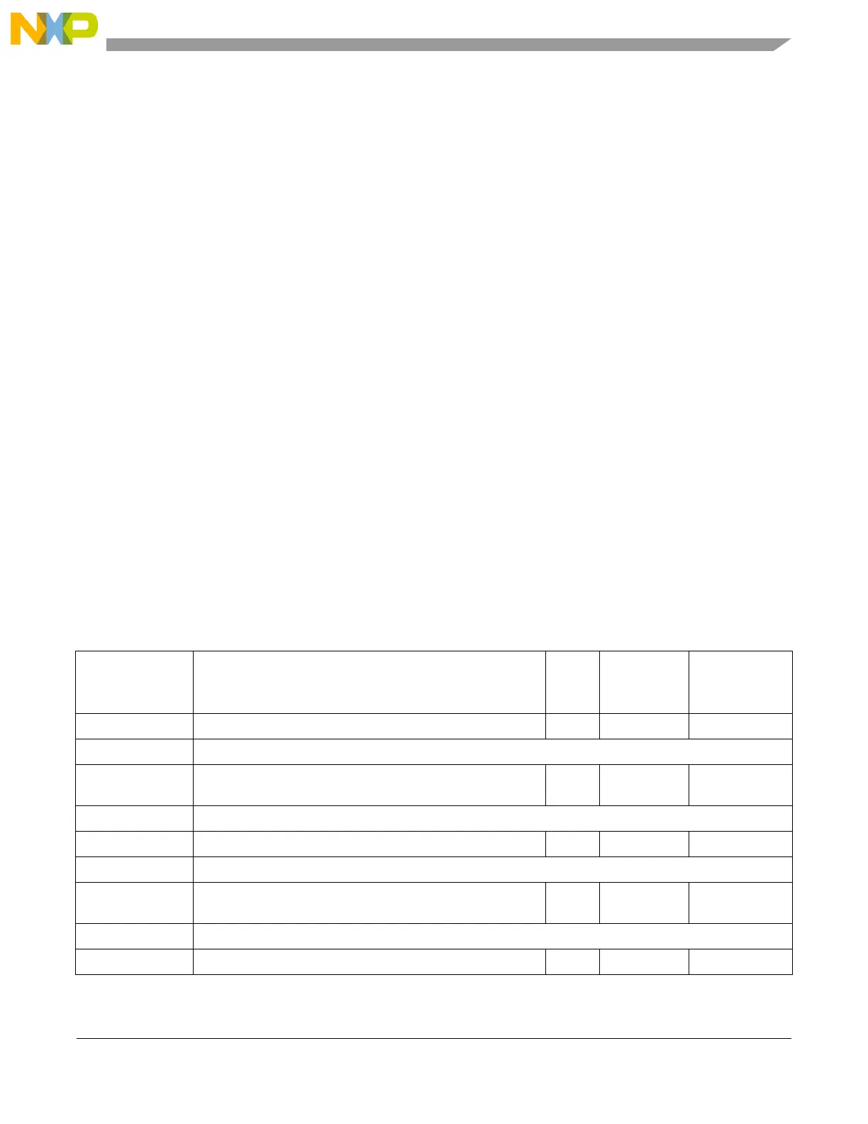
The memory map for the AXBS program-visible registers is shown in Table 16-3.
Table 16-3. AXBS Register Memory Map
Offset from
AXBS_BASE
(0xFFF0_4000)
Register Access Reset Value Section/Page
0x0000 XBAR_MPR0—Master Priority Register, Slave Port 0 R/W 0x5400_3210 16.2.1.1/16-4
0x0004–0x000F Reserved
0x0010 XBAR_SGPCR0—General-Purpose Control Register, Slave
Port 0
R/W 0x0000_0000 16.2.1.2/16-6
0x0014–0x00FF Reserved
0x0100 XBAR_MPR1—Master Priority Register, Slave Port 1 R/W 0x5400_3210 16.2.1.1/16-4
0x0104–0x010F Reserved
0x0110 XBAR_SGPCR1—General-Purpose Control Register, Slave
Port 1
R/W 0x0000_0000 16.2.1.2/16-6
0x0114–0x01FF Reserved
0x0200 XBAR_MPR2—Master Priority Register, Slave Port 2 R/W 0x5400_3210 16.2.1.1/16-4
 Loading...
