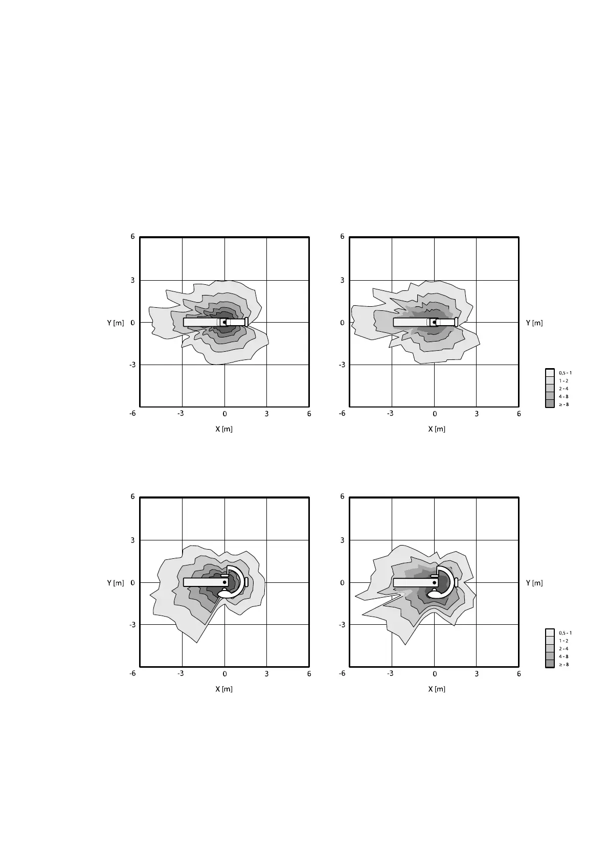
16.21.2 Isokerma Maps for C12/F12 System
The f
ollowing illustraons show normalized isokerma maps at 100 cm (39.37 in) and 150 cm (59.10 in)
above the oor, with swivel out.
The following technique factors are used:
• Fluoroscopy 120 kV
• Source-to-image distance 100 cm
• Field size 10 x 10 cm
• No addional lter
Frontal X-ray Direcon
Figure 136 Isok
erma map at 100 cm (le) and 150 cm (right) above the oor, μGy/(Gy x cm²)
Lateral X-ray Direcon
Figure 137 Isok
erma map at 100 cm (le) and 150 cm (right) above the oor, μGy/(Gy x cm²)
16.21.3 Isokerma Maps for F15 System and C20/F20 System
The following illustraons show normalized isokerma maps at 100 cm (39.37 in) and 150 cm (59.10 in)
above the oor, with swivel out.
Technical Informaon Protecon Against Stray Radiaon
Azurion Release 1.2 Ins
trucons for Use 315 Philips Healthcare 4522 203 52421