16-bit advanced control timer (TIM1) RM0016
162/449 Doc ID 14587 Rev 8
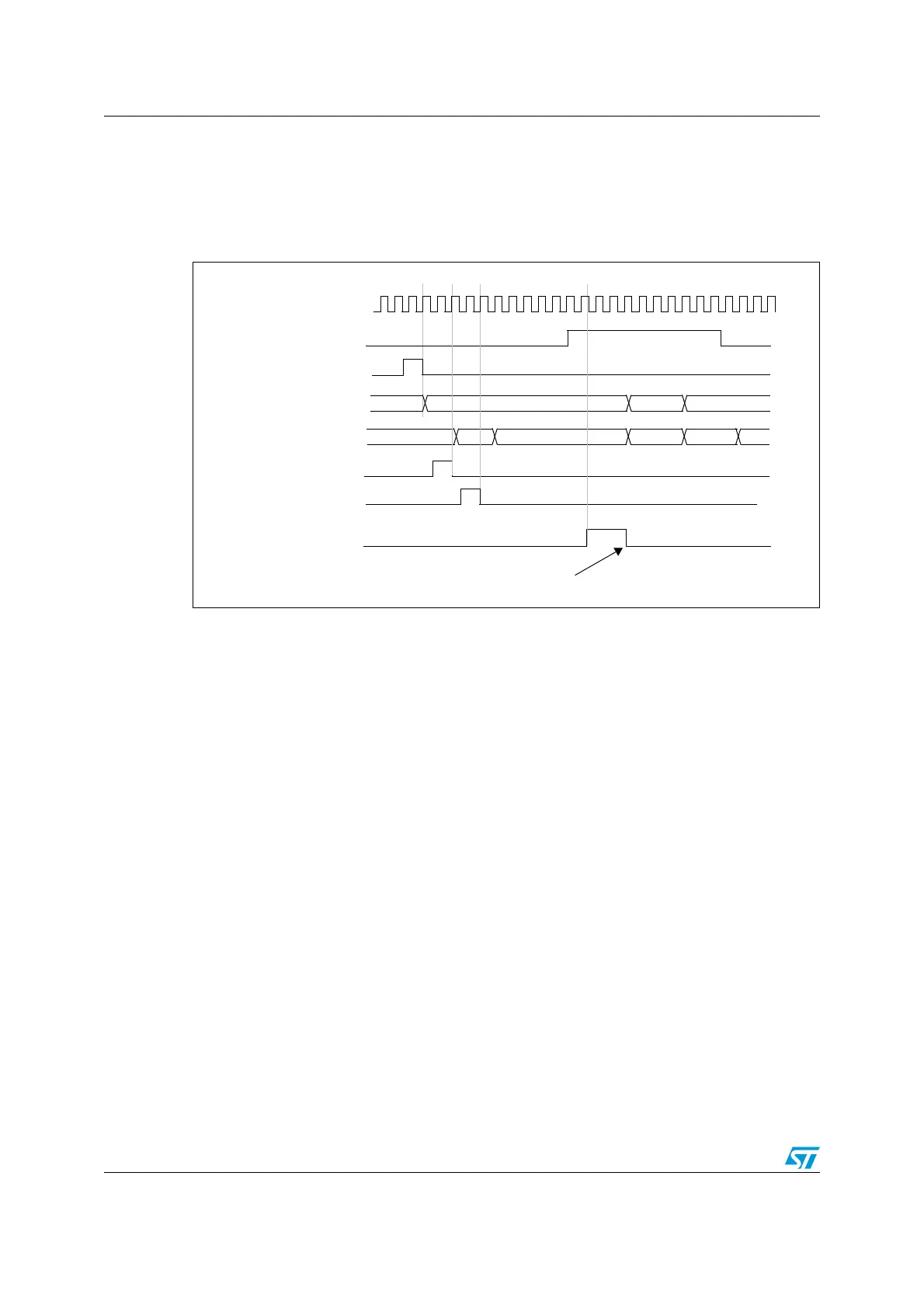
Example 2
As in the previous example, both counters can be initialized before starting to count.
Figure 59 shows the behavior, with the same configuration as in Figure 57, but, in trigger
standard mode instead of trigger gated mode (SMS = 110 in the TIM1_SMCR register).
Figure 59. Triggering timer B with counter enable CNT_EN of timer A
Starting 2 timers synchronously in response to an external trigger
Example
The enable of timer A is set when its TI1 input rises and the enable of timer B is set with the
enable of timer A (refer to Figure 55 for connections). To ensure the counters alignment,
timer A must be configured in master/slave mode (slave with respect to TI1, master with
respect to timer B).
1. Configure timer A master mode to send its enable as trigger output (MMS = 001 in the
TIMx_CR2 register).
2. Configure timer A slave mode to get the input trigger from TI1 (TS = 100 in the
TIMx_SMCR register).
3. Configure timer A in trigger mode (SMS = 110 in the TIMx_SMCR register)
4. Configure timer A in master/slave mode by writing MSM = 1 (TIMx_SMCR register)
5. Configure timer B to get the input trigger from timer A (TS = 001 in the TIMx_SMCR
register).
6. Configure timer B in trigger mode (SMS = 110 in the TIMx_SMCR register)
When a rising edge occurs on TI1 (timer A), both counters start counting synchronously on
the internal clock and both TIF flags are set.
Note: In this example both timers are initialized before starting (by setting their respective UG
bits). Both counters start from 0, but an offset can easily be inserted between them by
writing to any of the counter registers (TIMx_CNT). It can be seen that the master/slave
mode inserts a delay between CNT_EN and CK_PSC on timer A.
Timer B-TIF
Write TIF=0
75 00 01
f
MASTER
Timer A-CEN = CNT_EN
Timer A-CNT
Timer B-CNT
02
Timer A-UG
CD 00 E7 E8 EA
Timer B-UG
Timer B
write CNT
E9

 Loading...


