16-bit advanced control timer (TIM1) RM0016
158/449 Doc ID 14587 Rev 8
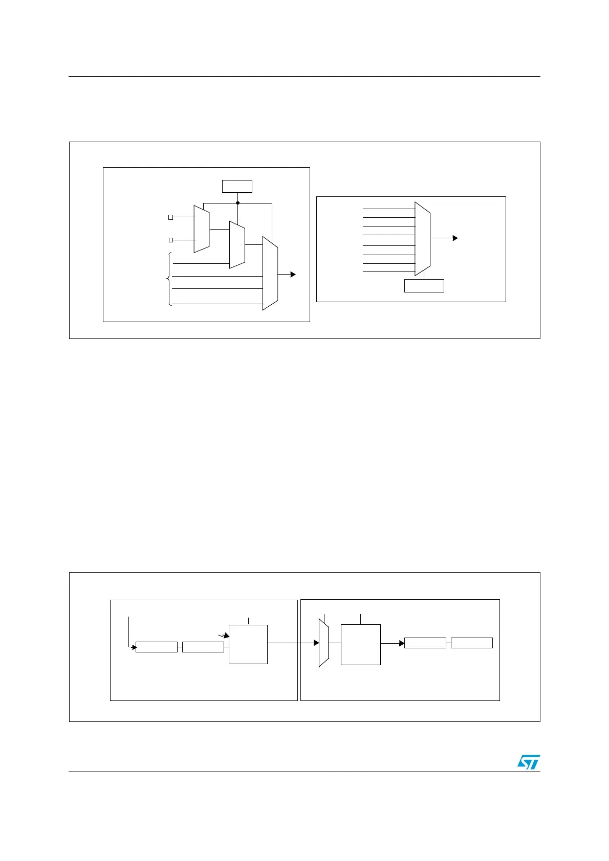
Figure 54 presents an overview of the trigger selection and the master mode selection
blocks.
Figure 54. Trigger/master mode selection blocks
Using one timer as prescaler for another timer
Refer to Figure 55 to see how timer A can be configured to act as a prescaler for timer B.
1. Configure timer A in master mode so that it outputs a periodic trigger signal on each
UEV. To configure that a rising edge is output on TRGO1 each time an update event is
generated, write MMS = 010 in the TIMx_CR2 register.
2. Connect the TRGO1 output of timer A to timer B, timer B must be configured in slave
mode using ITR1 as the internal trigger. Select this through the TS bits in the
TIMx_SMCR register (writing TS = 001).
3. Put the clock/trigger controller in external clock mode 1, by writing SMS = 111 in the
TIMx_SMCR register. This causes timer B to be clocked by the rising edge of the
periodic timer A trigger signal (which corresponds to the timer A counter overflow).
4. Enable both timers by setting their respective CEN bits (TIMx_CR1 register).
Note: If OCi is selected on timer A as trigger output (MMS = 1xx), its rising edge is used to clock
the counter of timer B.
Figure 55. Master/slave timer example
ITR2
TI1F_ED
ITR
TRC
TI1FP1
TI2FP2
From the Capture/
Compare block
ETRF
TRGI
TIMx_SMCR
TS[2:0]
TRIGGER SELECTION BLOCK
UG
CNT_EN
UEV
MATCH1
OC1REF
OC3REF
OC3REF
MASTER MODE SELECTION BLOCK
MMS[2:0]
TIMx_CR2
TRGO
TRGO from TIM5
ITR0
TRGO from TIM6
OC4REF
TRGO1
UEV
ITR1
PRESCALER
COUNTER
SMSTS
MMS
TIMER A TIMER B
MASTER
MODE
CONTROL
SLAVE
MODE
CONTROL
CK_PSC
PRESCALER
COUNTER
Clock
INPUT
SELECTION
TRIGGER

 Loading...


