Universal asynchronous receiver transmitter (UART) RM0016
354/449 Doc ID 14587 Rev 8
22.7.7 Control register 3 (UART_CR3)
Address offset: 0x06
Reset value: 0x00
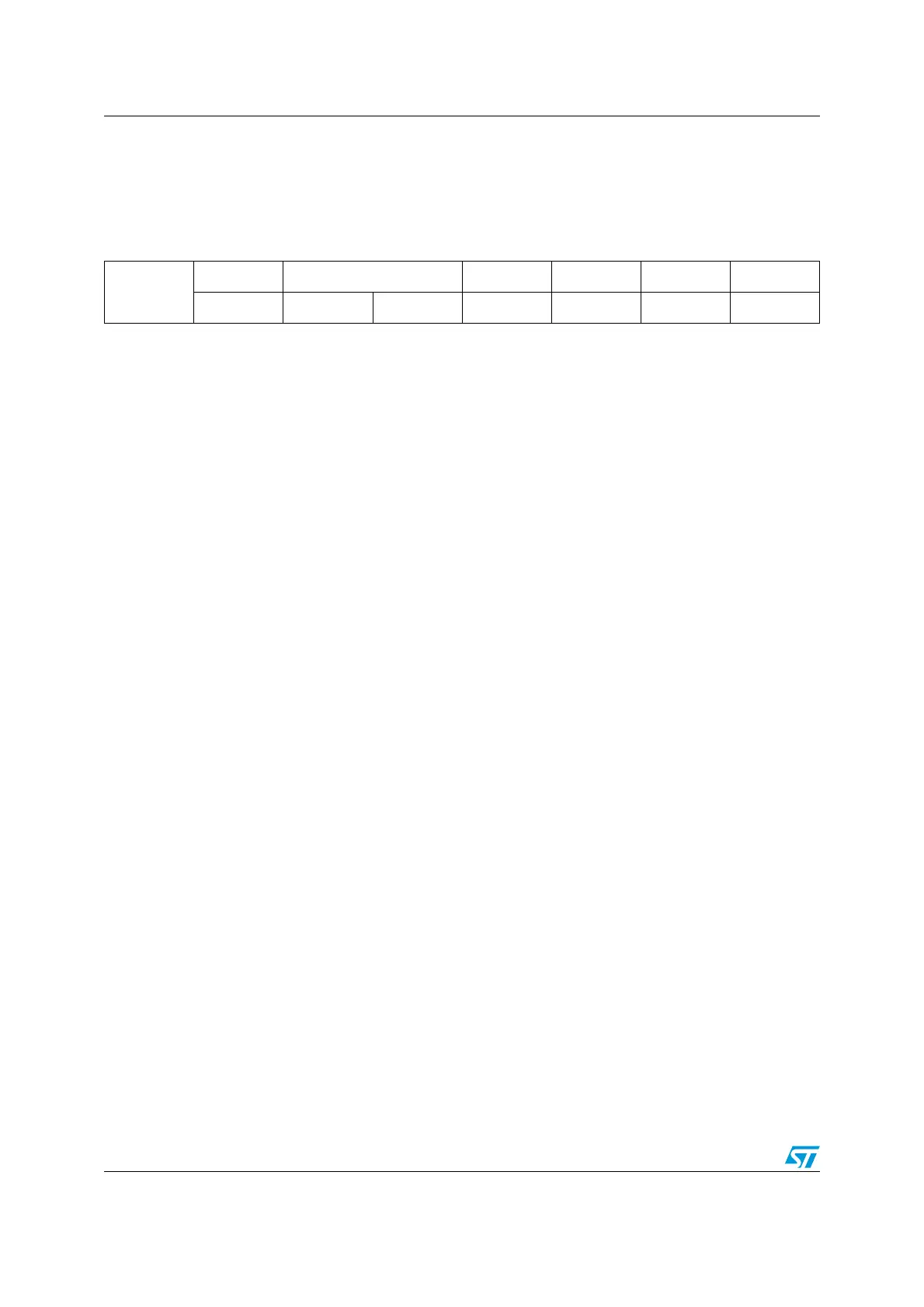
76543210
Reserved
LINEN STOP[1:0] CLKEN CPOL CPHA LBCL
rw rw rw rw rw rw rw
Bit 7 Reserved, must be kept cleared.
Bit 6 LINEN: LIN mode enable
This bit is set and cleared by software.
0: LIN mode disabled
1: LIN mode enabled
Bits 5:4 STOP: STOP bits.
These bits are used for programming the stop bits.
00: 1 Stop bit
01: Reserved
10: 2 Stop bits
11: 1.5 Stop bits
Note: For LIN slave mode, both bits should be kept cleared.
Bit 3 CLKEN: Clock enable
This bit allows the user to enable the SCLK pin.
0: SLK pin disabled
1: SLK pin enabled
Note: This bit is not available for UART3.
Bit 2 CPOL: Clock polarity
(1)
This bit allows the user to select the polarity of the clock output on the SCLK pin. It works in
conjunction with the CPHA bit to produce the desired clock/data relationship
0: SCK to 0 when idle
1: SCK to 1 when idle.
Note: This bit is not available for UART3.
Bit 1 CPHA: Clock phase
(1)
This bit allows the user to select the phase of the clock output on the SCLK pin. It works in
conjunction with the CPOL bit to produce the desired clock/data relationship
0: The first clock transition is the first data capture edge
1: The second clock transition is the first data capture edge
Note: This bit is not available for UART3.
Bit 0 LBCL: Last bit clock pulse.
(1)(2)
This bit allows the user to select whether the clock pulse associated with the last data bit transmitted
(MSB) has to be output on the SCLK pin.
0: The clock pulse of the last data bit is not output to the SCLK pin.
1: The clock pulse of the last data bit is output to the SCLK pin.
Note: This bit is not available for UART3.
1. These 3 bits (CPOL, CPHA, LBCL) should not be written while the transmitter is enabled.
2. The last bit is the 8th or 9th data bit transmitted depending on the 8 or 9 bit format selected by the M bit in the UART_CR1
register.

 Loading...


