Inter-integrated circuit (I
2
C) interface RM0016
306/449 Doc ID 14587 Rev 8
21.7.14 I
2
C register map and reset values
Bits 5:0 TRISE[5:0] Maximum rise time in Fast/Standard mode (Master mode)
These bits must be programmed with the maximum SCL rise time given in the I2C bus specification,
incremented by 1.
For instance: in standard mode, the maximum allowed SCL rise time is 1000 ns.
If the value in the I2C_FREQR register = 08h, then t
MASTER
= 125 ns therefore the TRISE[5:0] bits
must be programmed with 0x09.
(1000 ns / 125 ns = 8 + 1)
The filter value can also be added to TRISE[5:0].
If the result is not an integer, TRISE[5:0] must be programmed with the integer part, in order to
respect the t
HIGH
parameter.
Note: TRISE[5:0] must be configured only when the I2C is disabled (PE = 0).
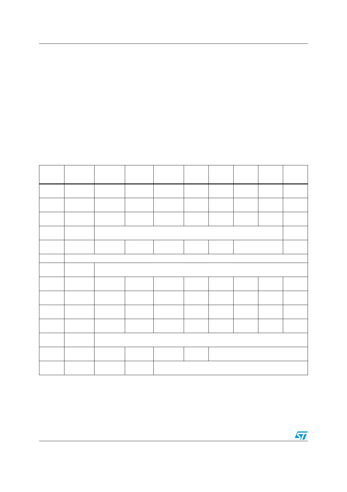
Table 51. I
2
C register map
Address
offset
Register
name
7 6 5 43210
0x00
I2C_CR1
Reset value
NO STRETCH
0
ENGC
0
-
0
-
0
-
0
-
0
-
0
PE
0
0x01
I2C_CR2
Reset value
SWRST
0
-
0
-
0
-
0
POS
0
ACK
0
STOP
0
START
0
0x02
I2C_FREQR
Reset value
-
0
-
0
FREQ5
0
FREQ4
0
FREQ3
0
FREQ2
0
FREQ1
0
FREQ0
0
0x03
I2C_OARL
Reset value
ADD[7:1]
0
ADD0
0
0x04
I2C_OARH
Reset value
ADDMODE
0
ADDCONF
0
-
0
-
0
-
0
ADD[9:8]
0
-
0
0x05 Reserved
0x06
I2C_DR
Reset value
DR[7:0]
0
0x07
I2C_SR1
Reset value
TXE
0
RXNE
0
-
0
STOPF
0
ADD10
0
BTF
0
ADDR
0
SB
0
0x08
I2C_SR2
Reset value
-
0
-
0
WUFH
0
-
0
OVR
0
AF
0
ARLO
0
BERR
0
0x09
I2C_SR3
Reset value
-
0
-
0
-
0
GENCALL
0
-
0
TRA
0
BUSY
0
MSL
0
0x0A
I2C_ITR
Reset value
-
0
-
0
-
0
--
0
--
0
ITBUFEN
0
ITEVTEN
0
ITERREN
0
0x0B
I2C_CCRL
Reset value
CCR[7:0]
0
0x0C
I2C_CCRH
Reset value
FS
0
DUTY
0
-
0
-
0
CCR[11:8]
0
0x0D
I2C_TRISER
Reset value
-
0
-
0
TRISE[5:0]
0

 Loading...


