16-bit advanced control timer (TIM1) RM0016
170/449 Doc ID 14587 Rev 8
The output compare mode is defined by the OCiM bits in the TIM1_CCMRi registers. The
active or inactive level polarity is defined by the CCiP bits in the TIM1_CCERi registers.
The TIM1_CCRi registers can be programmed with or without preload registers using the
OCiPE bits in the TIM1_CCMRi registers.
In output compare mode, the UEV has no effect on the OCiREF and OCi output. The timing
resolution is one count of the counter. Output compare mode can also be used to output a
single pulse.
Procedure
1. Select the counter clock (internal, external, or prescaler).
2. Write the desired data in the TIM1_ARR and TIM1_CCRi registers.
3. Set the CCiIE bits if an interrupt request is to be generated.
4. Select the output mode as follows:
– Write OCiM = 011 to toggle the OC
i output pin when CNT matches CCRi
– Write OCiPE = 0 to disable the preload register
– Write CCiP = 0 to select active high polarity
– Write CCiE = 1 to enable the output
5. Enable the counter by setting the CEN bit in the TIMx_CR1 register
The TIM1_CCRi registers can be updated at any time by software to control the output
waveform, provided that the preload registers are not enabled (OCiPE = 0). Otherwise, the
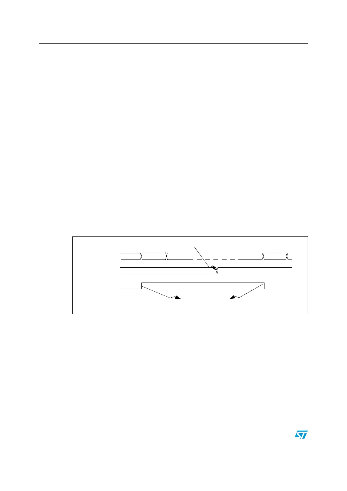
TIMx_CCRi shadow registers are updated only at the next UEV (see example in Figure 69.
Figure 69. Output compare mode, toggle on OC1
OC1REF=OC1
TIMx_CNT
B200 B201
0039
TIMx_CCR1
003A
Write B201h in the CC1R register
Match detected on OCR1
Interrupt generated if enabled
003B
B201
003A

 Loading...


