Beeper (BEEP) RM0016
120/449 Doc ID 14587 Rev 8
13 Beeper (BEEP)
13.1 Introduction
This function generates a beep signal in the range of 1, 2 or 4 kHz when the LS clock is
operating at a frequency of 128 kHz.
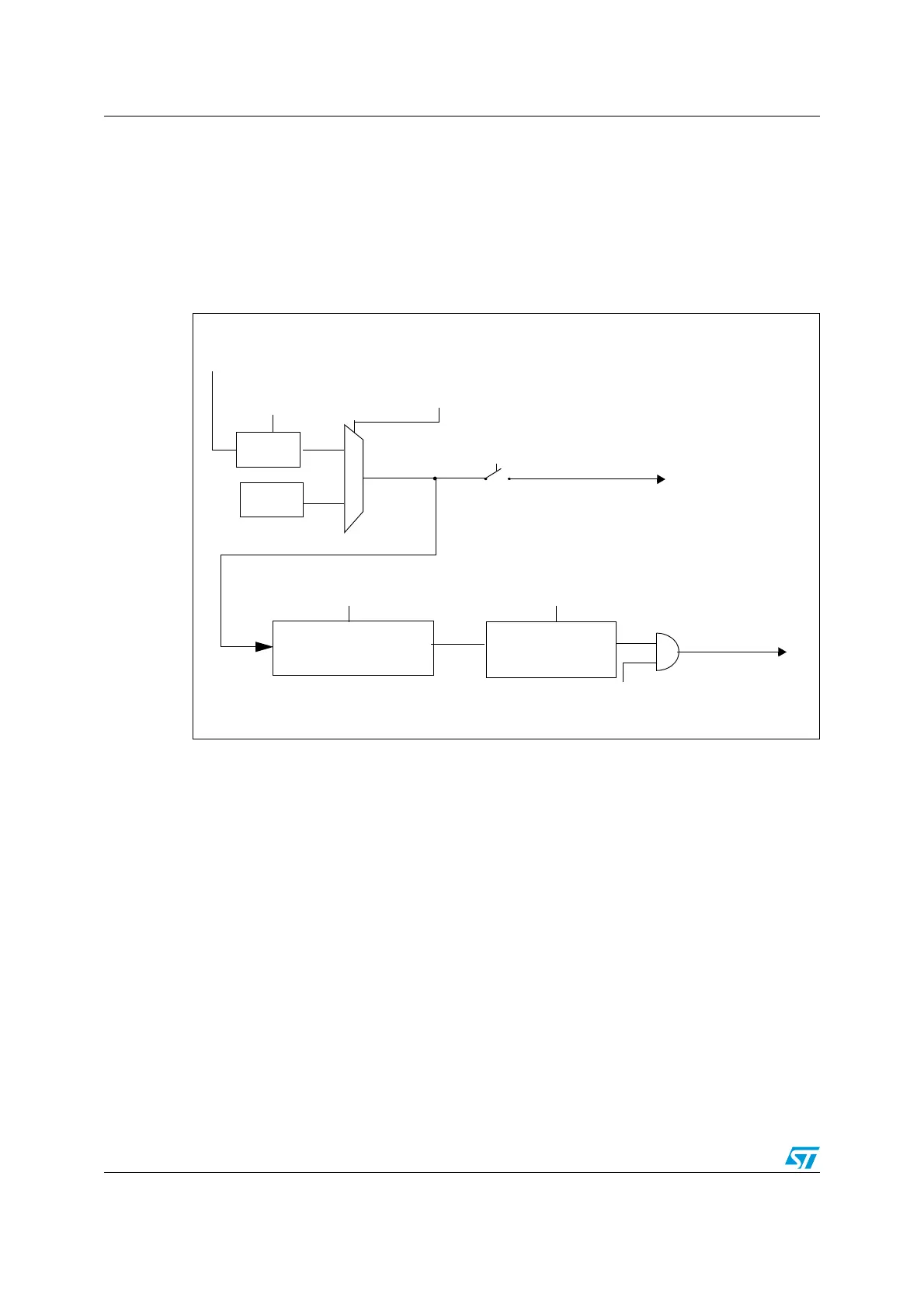
Figure 26. Beep block diagram
13.2 Beeper functional description
13.2.1 Beeper operation
To use the beep function, perform the following steps in order:
1. Calibrate the LS clock frequency as described in Section 13.2.2: Beeper calibration to
define BEEPDIV[4:0] value.
2. Select 1 kHz, 2 kHz or 4 kHz output frequency by writing to the BEEPSEL[1:0] bits in
the Beeper control/status register (BEEP_CSR).
3. Set the BEEPEN bit in the Beeper control/status register (BEEP_CSR) to enable the
LS clock source.
Note: The prescaler counter starts to count only if BEEPDIV[4:0] value is different from its reset
value, 0x1F.
BEEPEN
BEEP pin
LSI RC
128 kHz
MSR
To timer input capture
5-BIT BEEPER PROG
COUNTER
~8 kHz
3-BIT COUNTER
1 kHz, 2 kHz, 4 kHz
Prescaler
128 kHz LS clock
OPTION bit
HSE clock (4- 24 MHz)
OPTION bits
PRSC[1:0]
(for measurement)
CKAWUSEL
fLS
BEEPDIV[4:0] bits
BEEPSEL[1:0] bits

 Loading...


