Universal asynchronous receiver transmitter (UART) RM0016
336/449 Doc ID 14587 Rev 8
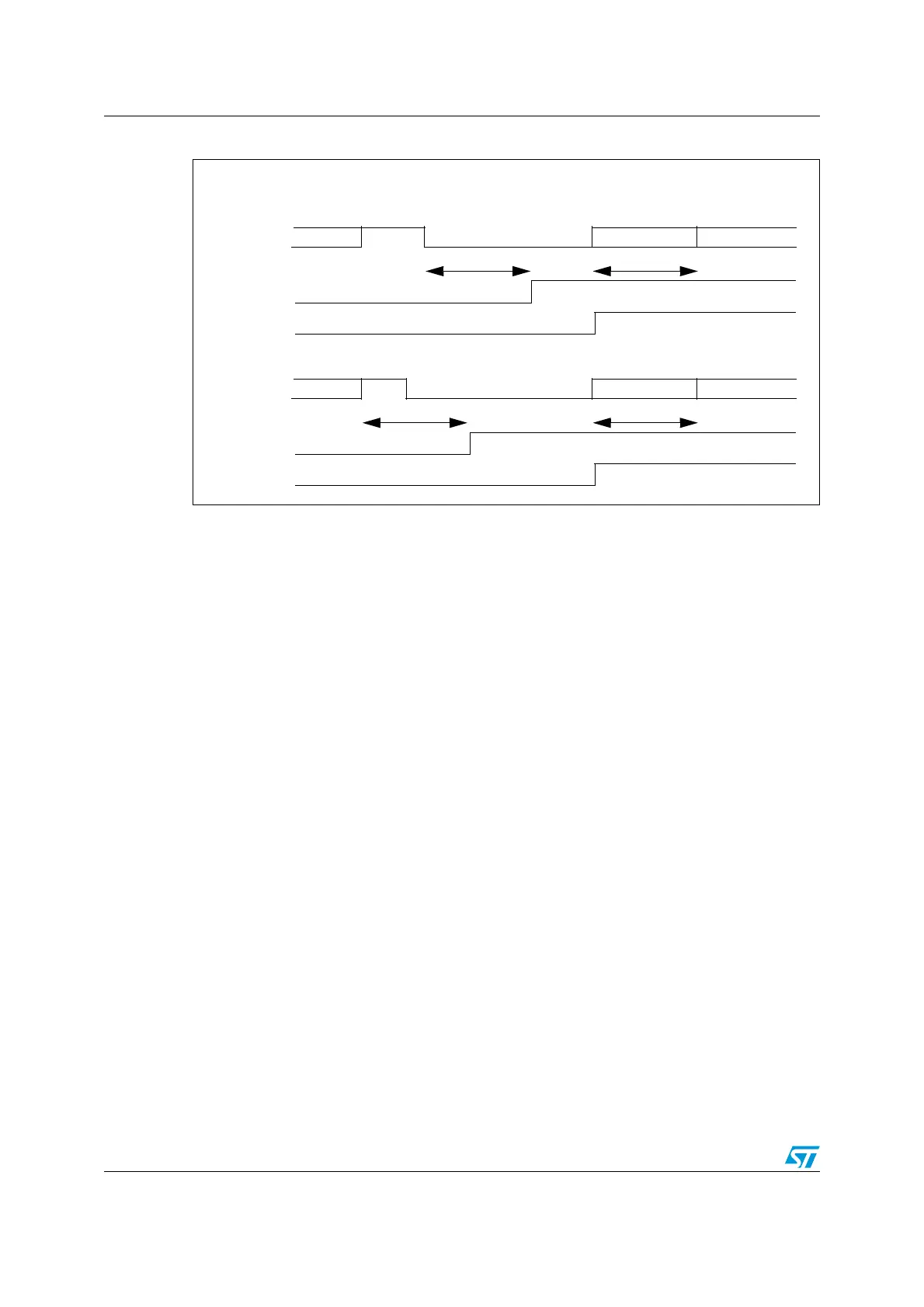
Figure 130. Break detection in LIN mode vs framing error detection
Response transmission (master is the publisher of the response)
The response is composed of bytes with a standard UART format: 8-bit data, 1 stop bit, no
parity.
In order to send n data bytes, the application must repeat the following sequence n times:
1. Write data in UART_DR register
2. Wait for RXNE flag in UART_SR register
3. Check for readback value by reading the UART_DR register
Response reception (master is the subscriber of the response)
In order to receive n data bytes, the application must repeat following sequence n times:
1. Wait for the RXNE flag in the UART_SR register
2. Read the UART_DR register
Discard response (slave to slave communication)
In case of slave to slave communication and if the master does not need to check errors in
the response, the application can ignore the RXNE flag till the next frame slot. The RXNE
and OR flags should be cleared before starting the next Break transmission.
Note: Receiving back a Break will also set the RXNE and FE flags before setting the LBDF flag.
Therefore, if the RX interrupt is used, it's better to disable it (by clearing the RIEN bit in the
UART_CR2 register) before sending the Break, to avoid an additional interrupt. In case of
slave to slave communication, RIEN bit can be cleared once the header has been
transmitted.
Case 1: break occurring after an Idle
IDLE data2 (0x55)data 1 data 3 (header)
In these examples, we suppose that LBDL=1 (11-bit break length), M=0 (8-bit data)
RX line
RXNE / FE
LBDF
1 data time 1 data time
Case 2: break occurring while a data is being received
data 2 data2 (0x55)data 1 data 3 (header)
RX line
RXNE / FE
LBDF
1 data time 1 data time
BREAK
BREAK

 Loading...


