RM0016 16-bit advanced control timer (TIM1)
Doc ID 14587 Rev 8 151/449
Procedure
Use the following procedure to configure the up-counter and, for example, to count in
response to a rising edge on the TI2 input:
1. Configure channel 2 to detect rising edges on the TI2 input by writing CC2S = 01 in the
TIM1_CCMR2 register.
2. Configure the input filter duration by writing the IC2F[3:0] bits in the TIM1_CCMR2
register (if no filter is needed, keep IC2F = 0000).
Note: The capture prescaler is not used for triggering, so it does not need t o be
configured. The CC2S bits do not need to be configured either as they only select the
input capture source.
3. Select rising edge polarity by writing CC2P = 0 in the TIM1_CCER1 register.
4. Configure the timer in external clock mode 1 by writing SMS = 111 in the TIM1_SMCR
register.
5. Select TI2 as the input source by writing TS = 110 in the TIM1_SMCR register.
6. Enable the counter by writing CEN = 1 in the TIM1_CR1 register.
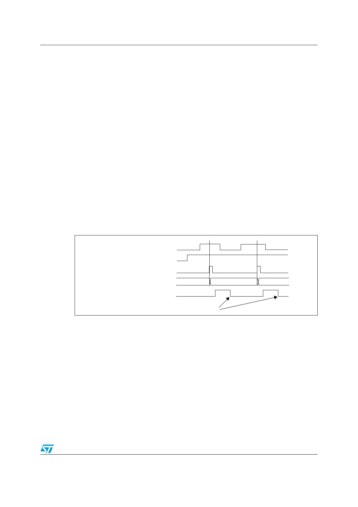
When a rising edge occurs on TI2, the counter counts once and the trigger flag is set (TIF bit
in the TIM1_SR1 register) and an interrupt request can be sent if enabled (depending on the
TIE bit in the TIM1_IER register).
The delay between the rising edge on TI2 and the actual reset of the counter is due to the
resynchronization circuit on TI2 input.
Figure 46. Control circuit in external clock mode 1
COUNTER CLOCK = CK_CNT = CK_PSC
COUNTER REGISTER
35 3634
TI2
CNT_EN
TIF
Write TIF=0

 Loading...


