RM0016 16-bit advanced control timer (TIM1)
Doc ID 14587 Rev 8 169/449
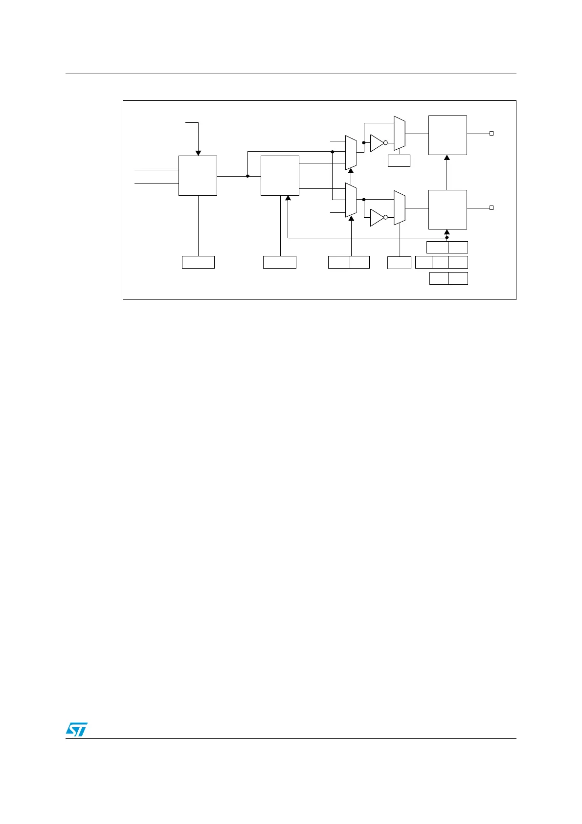
Figure 68. Detailed output stage of channel with complementary output (channel 1)
17.5.5 Forced output mode
In output mode (CCiS bits = 00 in the TIM1_CCMRi registers), each output compare signal
can be forced to high or low level directly by software, independently of any comparison
between the output compare register and the counter.
To force an output compare signal to its active level, write 101 in the OCiM bits in the
corresponding TIM1_CCMRi registers. OCiREF is forced high (OCiREF is always active
high) and the OCi output is forced high or low depending on the CCiP polarity bits.
For example, if CCiP = 0 (OCi active high) => OCi is forced high.
The OCiREF signal can be forced low by writing the OCiM bits to 100 in the TIMx_CCMRx
registers.
Nevertheless, the comparison between the TIM1_CCRi shadow registers and the counter is
still performed and allows the flag to be set. Interrupt requests can be sent accordingly. This
is described in the output compare mode section below.
17.5.6 Output compare mode
This function is used to control an output waveform or indicate when a period of time has
elapsed.
When a match is found between the capture/compare register and the counter:
● Depending on the output compare mode, the corresponding OCi output pin:
– Keeps its level (OCiM = 000),
– Is set active (OCiM = 001),
– Is set inactive (OCiM = 010)
– Toggles (OCiM = 011)
● A flag is set in the interrupt status register (CCiIF bits in the TIM1_SR1 register).
● An interrupt is generated if the corresponding interrupt mask is set (CCiIE bits in the
TIM1_IER register).
Output Mode
Counter > CCR1
Counter = CCR1
Controller
TIM1_CCMR1
OC1M[2:0]
OC1REF
Deadtime
Generator
OC1_DT
OC1N_DT
DTG[7:0]
TIM1_DTR
‘0’
‘0’
CC1E
TIM1_CCER1
CC1NE
0
1
CC1P
TIM1_CCER1
0
1
CC1NP
TIM1_CCER1
Output
Enable
Circuit
TIM1_CH1
Output
Enable
Circuit
CC1E
TIM1_CCER1
CC1NE
OSSI
TIM1_BKR
MOE OSSR
0x
10
11
11
01
x0
OIS1N
TIM1_OISR
OIS1
TIM1_CH1N
ETR

 Loading...


