RM0016 Clock control (CLK)
Doc ID 14587 Rev 8 85/449
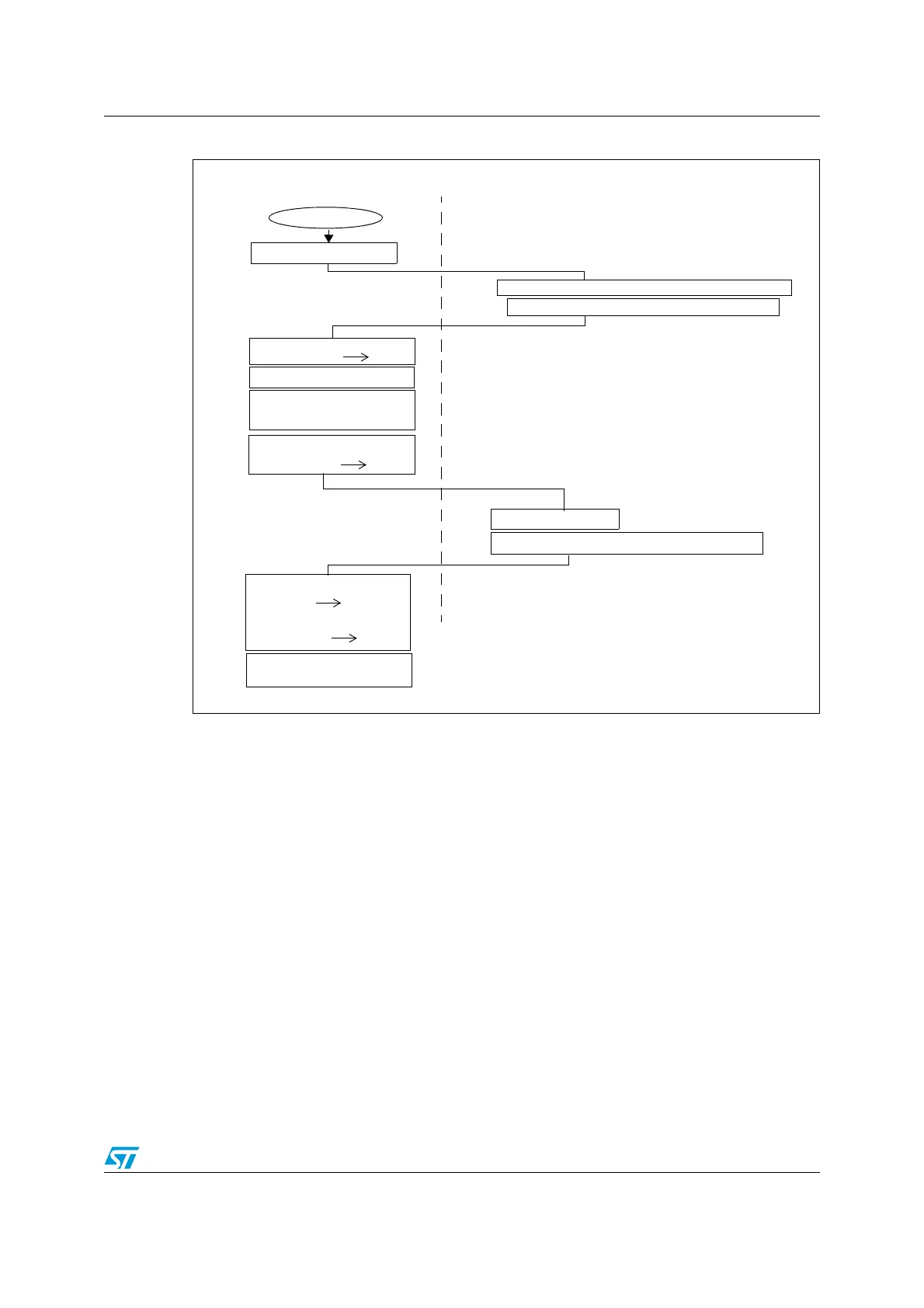
Figure 23. Clock switching flowchart (manual mode example)
9.3 Low speed clock selection
The Low speed clock source for the AWU or the independent watchdog can be LSI or HSE
divided according to the CKAWUSEL option bit. Refer to option bytes section in the
datasheet.
The division factor for HSE has to be programmed in the HSEPRSC[1:0] option bits Refer to
in the option bytes section of the datasheet. The goal is to get 128 kHz at the output of the
HSE prescaler.
9.4 CPU clock divider
The CPU clock (f
CPU
) is derived from the master clock (f
MASTER
), divided by a factor
programmed in the CPUDIV[2:0] bits in the Clock divider register (CLK_CKDIVR). Seven
division factors (1 to 128 in steps of power of 2) can be selected (refer to Figure 20).
The f
CPU
signal is the clock for both the CPU and the window watchdog.
Reset
MCU in Run mode with HSI/8
Write target clock source in CLK_SWR
Target clock source ready after
CLK_SWR
CLK_CMSR
SWBSY
0
Target clock source powered on
SWIF
SWBSY 1
stabilization time
Switch busy
1
MCU in Run mode
with new master clock source
SOFTWARE ACTIONHARDWARE ACTION
Reset switch busy flag
Update clock master status
Clear SWIF flag
Set SWIEN bit in CLK_SWCR to enable interrupt if suitable
Set SWEN bit in CLK_SWCR to execute switch
Interrupt if activated
Ready for the switch

 Loading...


