RM0016 Universal asynchronous receiver transmitter (UART)
Doc ID 14587 Rev 8 327/449
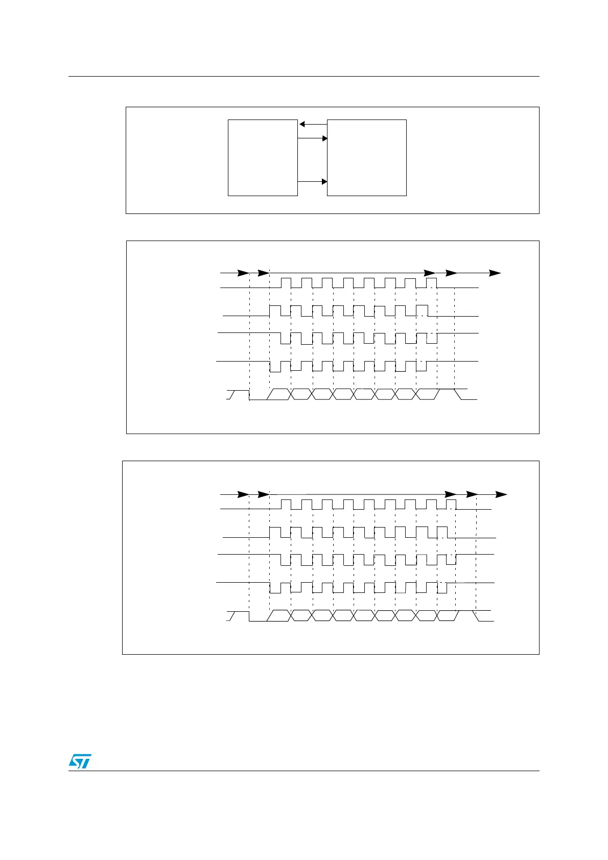
Figure 121. UART example of synchronous transmission
Figure 122. UART data clock timing diagram (M=0)
Figure 123. UART data clock timing diagram (M=1)
Data outRX
TX
SCLK
UART
Data in
Synchronous device
(for example slave SPI)
Clock
M=0 (8 data bits)
Clock (CPOL=0, CPHA=1)
Clock (CPOL=1, CPHA=0)
Clock (CPOL=1, CPHA=1)
Start LSB
MSB Stop
* LBCL bit controls last data clock pulse
Start
Idle or preceding
transmission
Data
Stop
Clock (CPOL=0, CPHA=0)
01 23456 7
*
*
*
*
Idle or next
transmission
Idle or next
M=1 (9 data bits)
Clock (CPOL=0, CPHA=1)
Clock (CPOL=1, CPHA=0)
Clock (CPOL=1, CPHA=1)
Start LSB
MSB Stop
* LBCL bit controls last data clock pulse
Start
Idle or preceding
transmission
Data
Stop
Clock (CPOL=0, CPHA=0)
01 23456 7
*
*
*
*
8
transmission

 Loading...


