RM0016 Universal asynchronous receiver transmitter (UART)
Doc ID 14587 Rev 8 341/449
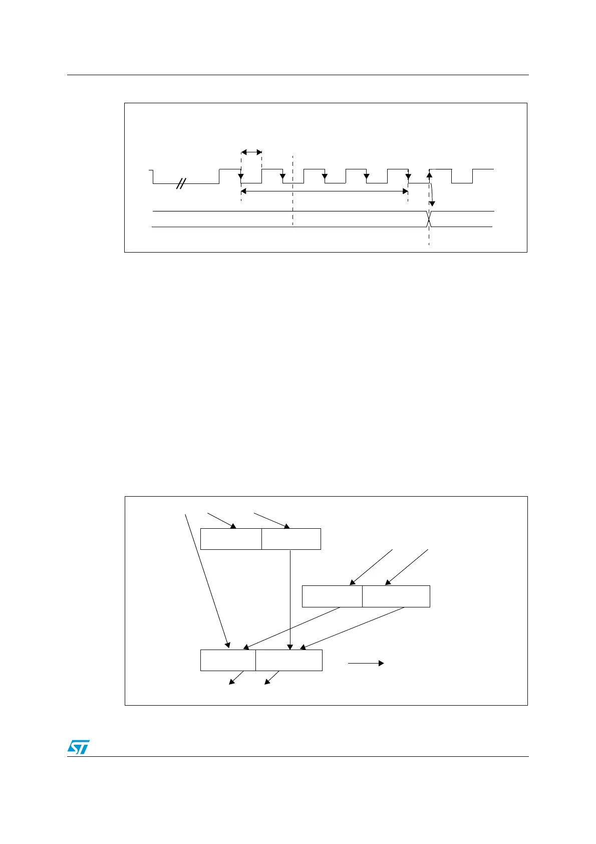
Figure 134. LIN synch field measurement
UARTDIV is an unsigned integer, coded in the BRR1 and BRR2 registers as shown in
Figure 118.
If LASE bit = 1 then UARTDIV is automatically updated at the end of each LIN Synch Field.
Three registers are used internally to manage the auto-update of the LIN divider
(UARTDIV):
● UARTDIV_NOM (nominal value written by software at UART_BRR1 and UART_BRR2
addresses)
● UARTDIV_MEAS (results of the Field Synch measurement)
● UARTDIV (used to generate the local baud rate)
The control and interactions of these registers are explained in Figure 135 and Figure 136.
They depend on the LDUM bit setting (LIN Divider Update Method)
As explained in Figure 135 and Figure 136, UARTDIV can be updated by two concurrent
actions: a transfer from UARTDIV_MEAS at the end of the LIN Sync Field and a transfer
from UARTDIV_NOM due to a software write to BRR1. If both operations occur at the same
time, the transfer from UARTDIV_NOM has priority.
Figure 135. UARTDIV read / write operations when LDUM = 0
LIN Break
Break
Bit0
Bit1
Bit2
Bit3
Bit4
Bit5
Bit6
Bit7
Start
Bit
Stop
Bit
Next
Start
Bit
LIN Synch Field
Measurement = 8.T
BR
= SM.T
MASTER
UARTDIV(n)
UARTDIV(n+1)
UARTDIV = T
BR
/ (T
MASTER
) = Rounding (SM / 128)
T
MASTER
= Master clock period
T
BR
= Baud Rate period
T
BR
T
BR
= UARTDIV.T
MASTER
SM = Synch Measurement Register (19 bits)
delim.
UARTDIV
UARTDIV_NOM
Baud Rate
Read UART2_BRR1
Write UART2_BRR2
Update
at end of
Synch Field
UARTDIV[3:0]
UARTDIV[11:4]
UARTDIV_MEAS
Write UART2_BRR1
Read UART2_BRR2
Generation
LIN Sync Field
Measurement
Write
UART2_BRR1
UARTDIV[15:2]
UARTDIV[3:0]
UARTDIV[7:0]
UARTDIV[15:12]
UARTDIV[3:0]
UARTDIV[11:4]
UARTDIV[15:12]

 Loading...


