RM0016 Interrupt controller (ITC)
Doc ID 14587 Rev 8 65/449
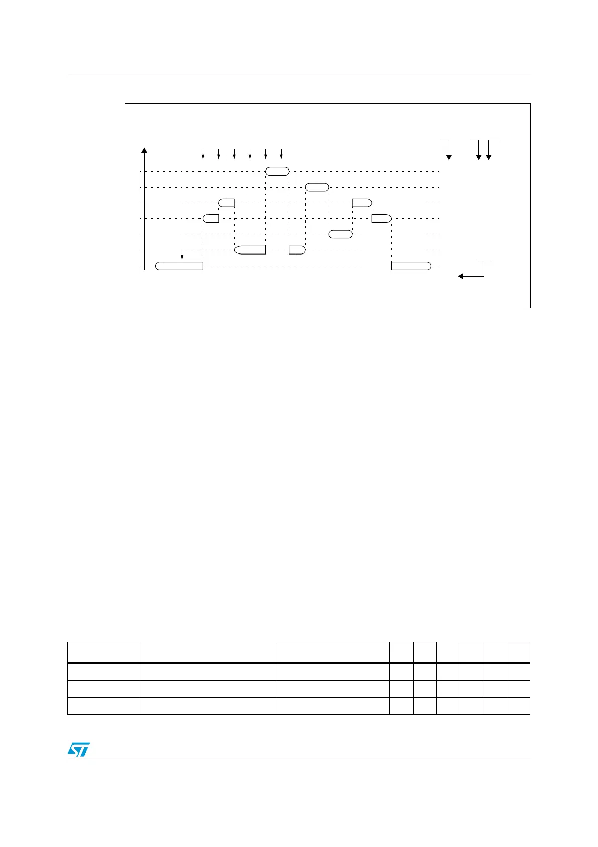
Figure 16. Nested interrupt management
6.6 External interrupts
Five interrupt vectors are dedicated to external Interrupt events:
● 5 lines on Port A: PA[6:2]
● 8 lines on Port B: PB[7:0]
● 8 lines on Port C: PC[7:0]
● 7 lines on Port D: PD[6:0]
● 8 lines on Port E: PE[7:0]
PD7 is the Top Level Interrupt source (TLI), except for 20-pin packages on which the Top
Level Interrupt source (TLI) can be available on the PC3 pin using an alternate function
remapping option bit. Refer to option bytes section in the product datasheet for more details.
To generate an interrupt, the corresponding GPIO port must be configured in input mode
with interrupts enabled. Refer to the register description in the GPIO chapter for details.
The interrupt sensitivity must be configured in the external interrupt control register 1
(EXTI_CR1) and external interrupt control register 2 (EXTI_CR2) (see Section 6.9.3 and
Section 6.9.4.).
6.7 Interrupt instructions
Table 1 1 shows the interrupt instructions.
MAIN
IT2
TRAP
MAIN
IT0
IT2
IT1
IT4
TRAP
IT3
IT0
HARDWARE PRIORITY
3
2
1
3
3
3/0
3
11
00
01
11
11
11
RIM
IT1
IT4
IT4
IT1
IT2
IT3
I1 I0
11 / 10
10
SOFTWARE
PRIORITY
LEVEL
USED STACK = 20 BYTES
Table 11. Dedicated interrupt instruction set
Instruction New description Function/example I1 H I0 N Z C
HALT Entering Halt mode 1 0
IRET Interrupt routine return Pop CCR, A, X, Y, PC I1 H I0 N Z C
JRM Jump if I1:0=11 (level 3) I1:0=11 ?

 Loading...


