16-bit advanced control timer (TIM1) RM0016
168/449 Doc ID 14587 Rev 8
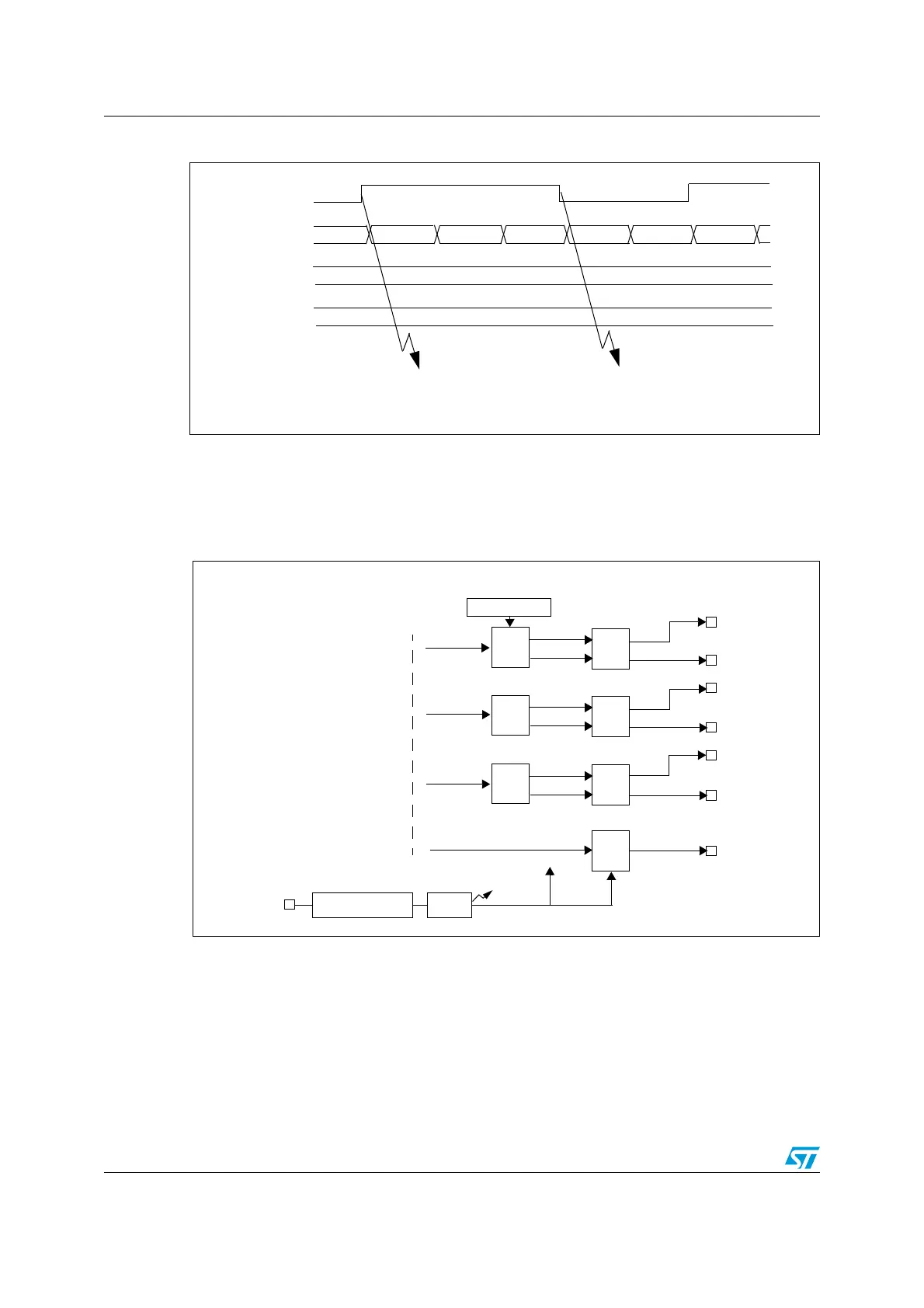
Figure 66. PWM input signal measurement example
17.5.4 Output stage
The output stage generates an intermediate waveform called OCiREF (active high) which is
then used for reference. Break functions and polarity act at the end of the chain.
Figure 67. Channel output stage block diagram
TI1
TIM1_CNT
0000 0001 0002 0003 0004 00000004
TIM1_CCR1
TIM1_CCR2
0004
0002
IC1 Capture
period measurement
reset counter
IC2 Capture
pulse width measurement
OC1REF
OC2REF
OC3REF
DTG
DTG registers
DTG
DTG
output
control
output
control
output
control
OC1
OC2
OC3
TIM1_CH1
TIM1_CH2
TIM1_CH3
TIM1_CH3N
OC3N
TIM1_CH2N
OC2N
TIM1_CH1N
OC1N
OC4REF
output
control
TIM1_CH4
OC4
BI
Polarity Selection
Enable
TIM1_BKIN
From capture/compare
channels
Deadtime generation

 Loading...


