Serial peripheral interface (SPI) RM0016
264/449 Doc ID 14587 Rev 8
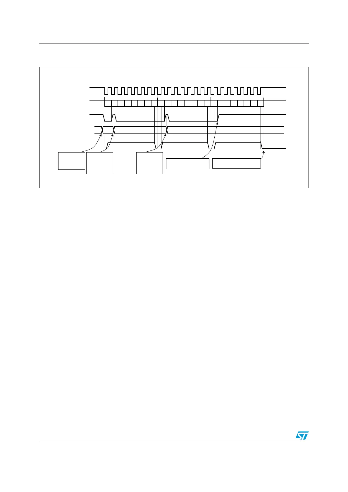
Figure 97. TXE/BSY in slave transmit-only mode (BDM = 0 and RXONLY = 0).
Case of continuous transfers
Bidirectional transmit procedure (BDM = 1 and BDOE = 1)
In this mode, the procedure is similar to the Transmit-only procedure except that the BDM
and BDOE bits must both be set in the SPI_CR2 register before enabling the SPI.
Unidirectional receive-only procedure (BDM = 0 and RXONLY = 1)
In this mode, the procedure can be reduced as described below (see Figure 98):
1. Set the RXONLY bit in the SPI_CR2 register
2. Enable the SPI by setting bit SPE to 1:
a) In master mode, this immediately activates the generation of the SCK clock, and
data is received serially until the SPI is disabled (SPE = 0).
b) In slave mode, data are received when the SPI master device drives NSS low and
generates the SCK clock.
3. Wait until RXNE =1 and read the SPI_DR register to get the received data (this clears
the RXNE bit). Repeat this operation for each data to be received.
This procedure can be also implemented using dedicated interrupt subroutines launched at
each rising edge of the RXNE flag.
Note: If it is required to disable the SPI after the last transfer, follow the recommendation described
in Section 20.3.8: Disabling the SPI on page 268.
0xF1
Tx Buffer
TXE flag
0xF2
BSY flag
0xF3
software writes
0xF1 in SPI_DR
software waits
until TXE=1 and
writes 0xF2 in
SPI_DR
set by hw
cleared by sw
set by hw
cleared by sw
set by hw
set by hw
SCK
reset by hw
Example in slave mode with CPOL=1, CPHA=1
(write SPI_DR)
MISO/MOSI (out)
DATA 1 = 0xF1 DATA 2 = 0xF2
DATA 3 = 0xF3
software waits
until TXE=1 and
writes 0xF3 in
SPI_DR
software waits until BSY=0software waits until TXE=1
b0 b1 b2 b3 b4 b5 b6 b7 b0 b1 b2 b3 b4 b5 b6 b7 b0 b1 b2 b3 b4 b5 b6 b7

 Loading...


