RM0016 Reset (RST)
Doc ID 14587 Rev 8 73/449
8 Reset (RST)
There are 9 reset sources:
● External reset through the NRST pin
● Power-on reset (POR)
● Brown-out Reset (BOR)
● Independent watchdog reset (IWDG)
● Window watchdog reset (WWDG)
● Software reset
● SWIM reset
● Illegal opcode reset
● EMC reset: generated if critical registers are corrupted or badly loaded
These sources act on the RESET
pin and it is always kept low during the delay phase. The
RESET service routine vector is fixed at address 6000h in the memory map.
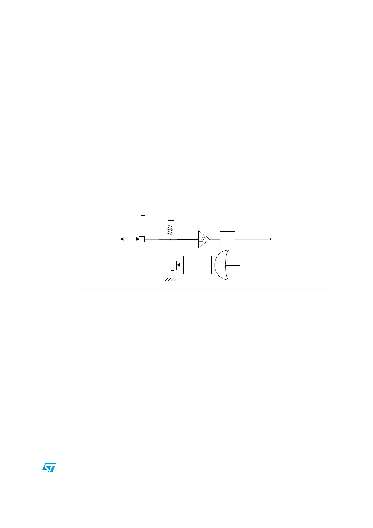
Figure 18. Reset circuit
8.1 “Reset state” and “under reset” definitions
When a reset occurs, there is a reset phase from the external pin pull-down to the internal
reset signal release. During this phase, the microcontroller sets some hardware
configurations before going to the reset vector.
At the end of this phase, most of the registers are configured with their “reset state” values.
During the reset phase, i.e. “under reset”, some pin configurations may be different from
their “reset state” configuration.
8.2 Reset circuit description
The NRST pin is both an input and an open-drain output with integrated R
PU
weak pull-up
resistor.
The low pulse of duration t
INFP(NRST)
on the NRST pin generates an external reset. The
reset detection is asynchronous and therefore the MCU can enter reset even in Halt mode.
The NRST pin also acts as an open-drain output for resetting external devices.
NRST
R
PU
V
DD_IO
PULSE
GENERATOR
SWIM RESET
EXTERNAL
RESET
(min 20 µs)
SYSTEM NRESET
ILLEGAL OPCODE RESET
EMC RESET
IWDG/WWDG/SOFTWARE RESET
POR/BOR RESET
Filter
(typ 45 kΩ)

 Loading...


