RM0016 16-bit advanced control timer (TIM1)
Doc ID 14587 Rev 8 145/449
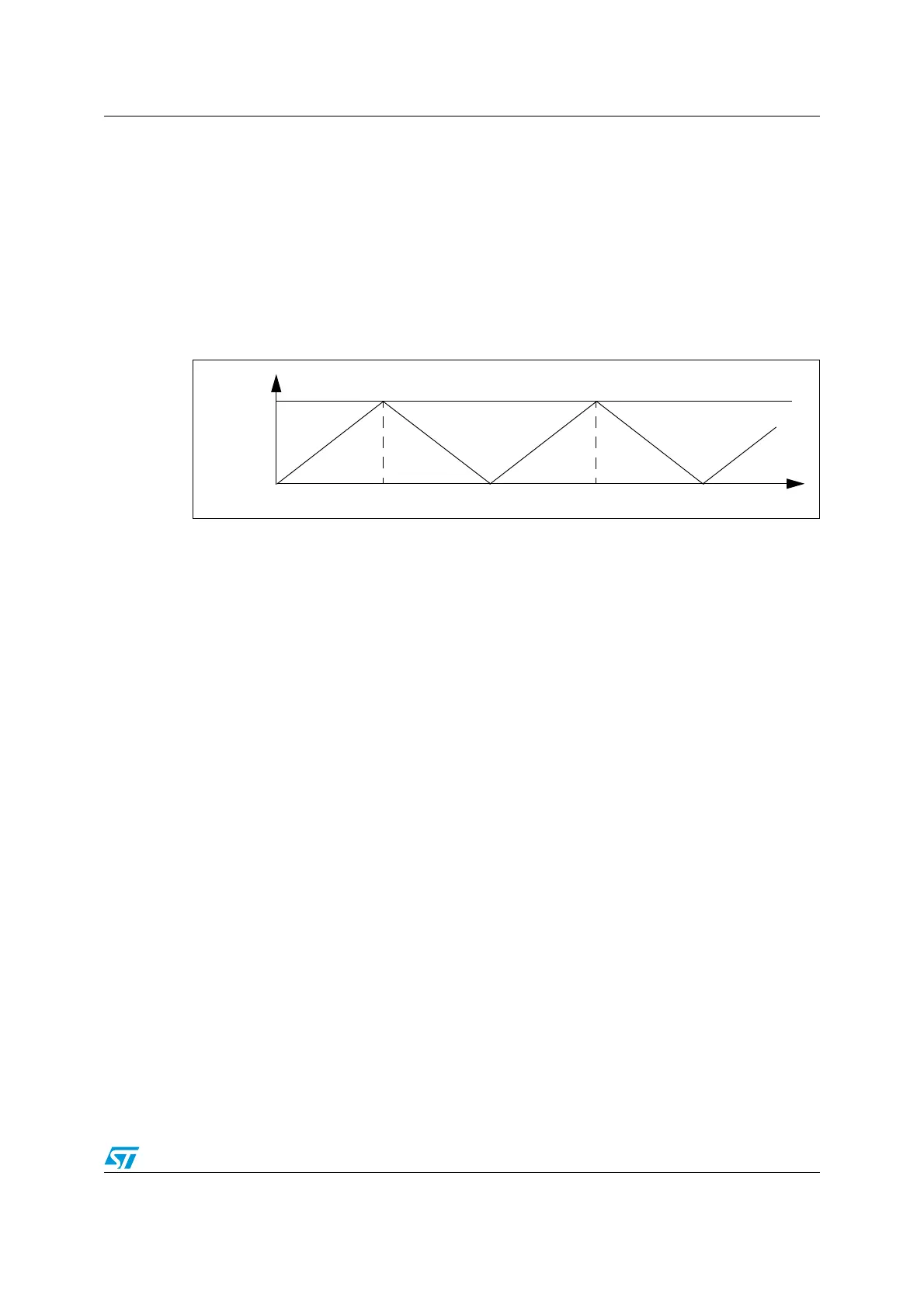
17.3.6 Center-aligned mode (up/down counting)
In center-aligned mode, the counter counts from 0 to the auto-reload value of -1 (content of
the TIM1_ARR register). This generates a counter overflow event. The counter then counts
down to 0 and generates a counter underflow event. After this, the counter restarts counting
from 0.
In this mode, the direction bit (DIR) in the TIM1_CR1 register cannot be written. It is updated
by hardware and gives the current direction of the counter.
The Figure 40 shows an example of this counting mode.
Figure 40. Counter in center-aligned mode
If the timer has a repetition counter (as in TIM1), the UEV is generated after up and down
counting and repeated for the number of times programmed in the repetition counter register
(TIM1_RCR). Otherwise, the UEV is generated at each counter overflow and at each
counter underflow.
Setting the UG bit in the TIM1_EGR register (by software or by using the clock/trigger mode
controller) also generates an update event. In this case, the counter and the prescaler
restart counting from 0.
The UEV can be disabled by software by setting the UDIS bit in the TIM1_CR1 register. This
is to avoid updating the shadow registers while writing new values in the preload registers.
In this way, no update event occurs until the UDIS bit is written to 0. However, the counter
continues counting up and down, based on the current auto-reload value. In timers with a
repetition counter, the new update rate is used because the repetition register is not double
buffered. For this reason, care must be taken when changing the update rate.
In addition, if the URS bit in the TIM1_CR1 register is set, setting the UG bit generates a
UEV without setting the UIF flag. Consequently, no interrupt request is sent. This avoids
generating both update and capture interrupts when clearing the counter on the capture
event.
When an update event occurs, all registers are updated and the update flag (the UIF bit in
the TIM1_SR1 register) is set (depending on the URS bit).
● The buffer of the prescaler is reloaded with the preload value (content of the
TIM1_PSCR register).
● The auto-reload shadow register is updated with the preload value (content of the
TIM1_ARR register). Note that if the update source is a counter overflow, the auto-
reload is updated before the counter is reloaded, so that the next period is the expected
one (the counter is loaded with the new value).
Below are some examples of the counter behavior for different clock frequencies.
Counter
Time
TIMx_ARR
UnderflowOverflow Overflow
Underflow
0

 Loading...


