RM0016 Central processing unit (CPU)
Doc ID 14587 Rev 8 25/449
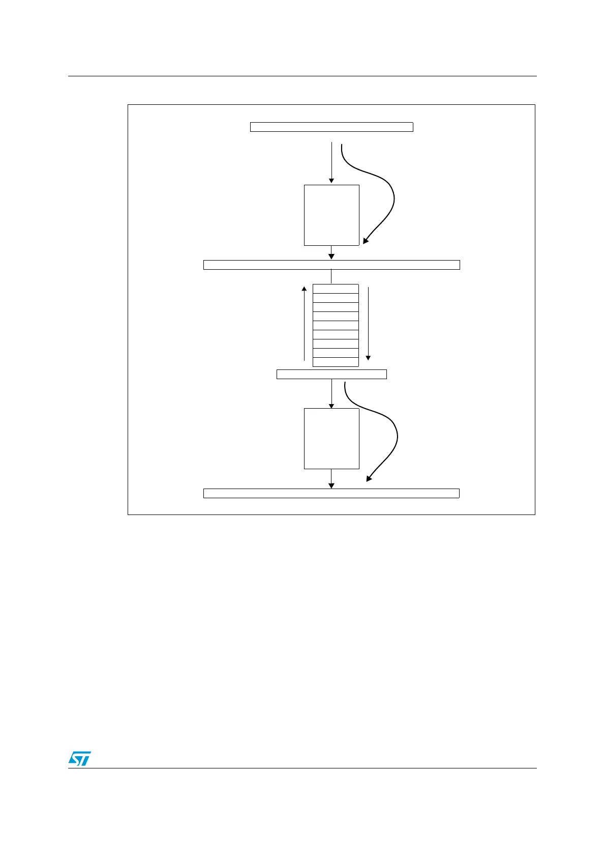
Figure 2. Stacking order
Condition code register (CC)
The condition code register is an 8-bit register which indicates the result of the instruction
just executed as well as the state of the processor. The 6th bit (MSB) of this register is
reserved. These bits can be individually tested by a program and specified action taken as a
result of their state. The following paragraphs describe each bit:
● V: Overflow
When set, V indicates that an overflow occurred during the last signed arithmetic operation,
on the MSB result bit. See the INC, INCW, DEC, DECW, NEG, NEGW, ADD, ADDW, ADC,
SUB, SUBW, SBC, CP, and CPW instructions.
● I1: Interrupt mask level 1
The I1 flag works in conjunction with the I0 flag to define the current interruptability level as
shown in Table 1 . These flags can be set and cleared by software through the RIM, SIM,
HALT, WFI, IRET, TRAP, and POP instructions and are automatically set by hardware when
entering an interrupt service routine.
JUMP TO INTERRUPT ROUTINE GIVEN BY THE INTERRUPT VECTOR
INTERRUPT GENERATION (execute pipeline)
YH
YL
PCE
PCL
CC
STACK
(PUSH)
UNSTACK
INTERRUPT
RETURN
PCH
JUMP TO THE ADDRESS GIVEN BY PROGRAM COUNTER (Reload Pipeline)
IRET INSTRUCTION
(POP)
9 CPU CYCLES
9 CPU CYCLES
POP PCL
POP PCH
POP PCE
POP Y
POP X
POP A
POP CC
A
XH
XL
PUSH PCL
PUSH PCH
PUSH PCE
PUSH Y
PUSH X
PUSH A
PUSH CC
Complete instruction in execute stage (1-6 cycles latency)

 Loading...


