RM0016 Interrupt controller (ITC)
Doc ID 14587 Rev 8 59/449
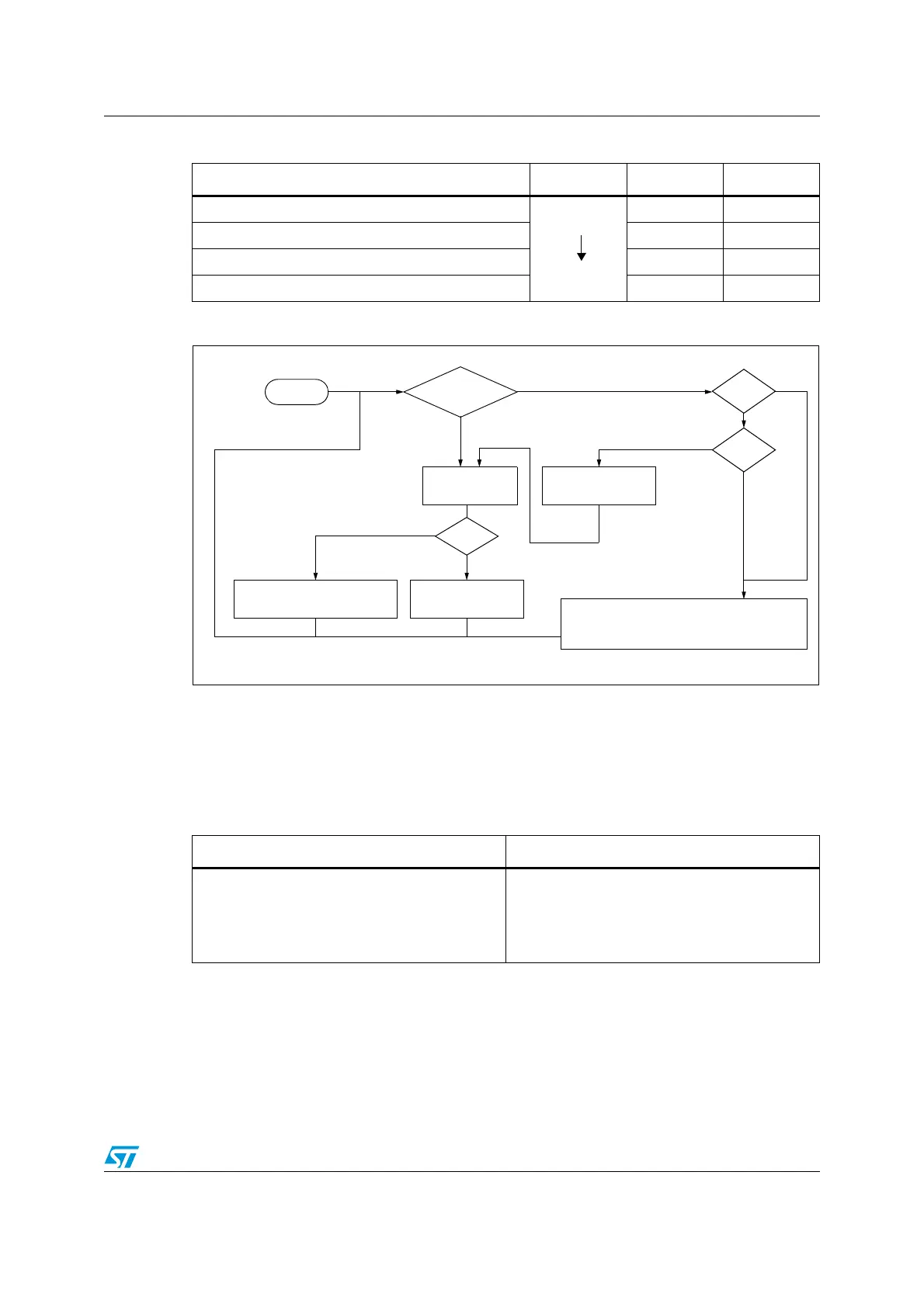
Figure 13. Interrupt processing flowchart
Caution: If the interrupt mask bits I0 and I1 are set within an interrupt service routine (ISR) with the
instruction SIM, removal of the interrupt mask with RIM causes the software priority to be
set to level 0.
To restore the correct priority when disabling and enabling interrupts inside an ISR, follow
the procedures presented in Ta ble 8 for disabling and enabling the interrupts.
Table 8. Software priority levels
Software priority Level I1 I0
Level 0 (main)
Low
High
10
Level 1 0 1
Level 2 0 0
Level 3 (= software priority disabled) 1 1
“IRET”
RESTORE PC, X, Y, A, CCR
STACK PC, X, Y, A, CCR
LOAD I1:0 FROM INTERRUPT SW REG.
FETCH NEXT
RESET
TRAP
PENDING
INSTRUCTION
I1:0
FROM STACK
LOAD PC FROM INTERRUPT VECTOR
Y
N
Y
N
Y
N
Interrupt has the same or a
lower software priority
THE INTERRUPT
STAYS PENDING
than current one
Interrupt has a higher
software priority
than current one
EXECUTE
INSTRUCTION
INTERRUPT
Table 9. Interrupt enabling/disabling inside an ISR
Disabling the interrupts Enabling the interrupts
#asm
PUSH CC
POP ISR_CC
(1)
SIM
#endasm
1. IRS_CC is a variable which stores the current value of the CC register.
#asm
PUSH ISR_CC
(1)
POP CC
#endasm

 Loading...


