16-bit advanced control timer (TIM1) RM0016
176/449 Doc ID 14587 Rev 8
Deadtime insertion is enabled by setting the CCi E and CCi NE bits, and the MOE bit if the
break circuit is present. Each channel embeds an 8-bit deadtime generator. It generates two
outputs: OCi and OCi N from a reference waveform, OCi REF. If OCi and OCi N are active
high:
● The OCi output signal is the same as the reference signal except for the rising edge,
which is delayed relative to the reference rising edge.
● The OCi N output signal is the opposite of the reference signal except for the rising
edge, which is delayed relative to the reference falling edge.
If the delay is greater than the width of the active output (OCi or OCi N), the corresponding
pulse is not generated.
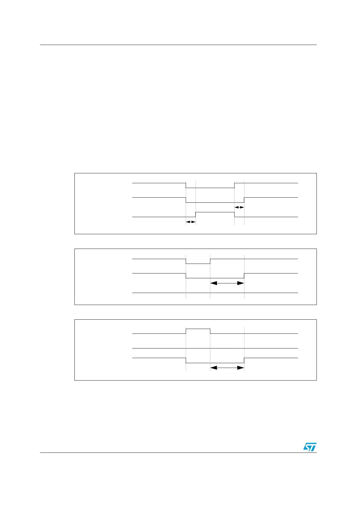
Figure 73, Figure 74, and Figure 75 show the relationships between the output signals of
the deadtime generator and the reference signal OCi REF (where CCi P = 0, CCi NP = 0,
MOE = 1, CCi E = 1, and CCi NE = 1 in these examples)
Figure 73. Complementary output with deadtime insertion
Figure 74. Deadtime waveforms with a delay greater than the negative pulse
Figure 75. Deadtime waveforms with a delay greater than the positive pulse
The deadtime delay is the same for each of the channels and is programmable with the DTG
bits in the TIM1_DTR register. Refer to Section 17.7.31: Deadtime register (TIM1_DTR) on
page 212 for delay calculation.

 Loading...


