RM0016 16-bit advanced control timer (TIM1)
Doc ID 14587 Rev 8 167/449
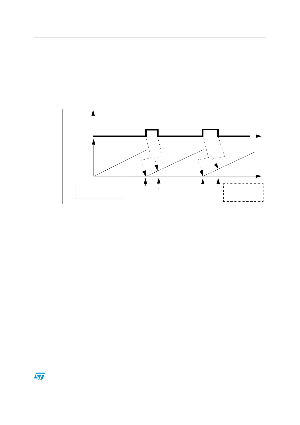
PWM input signal measurement
This mode is a particular case of input capture mode (see Figure 65). The procedure is the
same except:
● Tw o ICi signals are mapped on the same TIi input
● These two ICi signals are active on edges with opposite polarity
● One of the two TIiFP signals is selected as trigger input and the clock/trigger controller
is configured in trigger reset mode.
Figure 65. PWM input signal measurement
Procedure
Depending on the f
MASTER
frequency and prescaler value, the period (in the TIM1_CCR1
register) can be measured and the duty cycle (in the TIM1_CCR2 register) of the PWM can
be applied on TI1 using the following procedure:
1. Select the active input capture or trigger input for TIM1_CCR1 by writing the CC1S bits
to 01 in the TIM1_CCMR1 register (TI1FP1 selected).
2. Select the active polarity for TI1FP1 (used for both capture and counter clear in
TIMx_CCR1) by writing the CC1P bit to 0 (TI1FP1 active on rising edge).
3. Select the active input for TIM1_CCR2 by writing the CC2S bits to 10 in the
TIM1_CCMR2 register (TI1FP2 selected).
4. Select the active polarity for TI1FP2 (used for capture in TIM1_CCR2) by writing the
CC2P bit to 1 (TI1FP2 active on falling edge).
5. Select the valid trigger input by writing the TS bits to 101 in the TIM1_SMCR register
(TI1FP1 selected).
6. Configure the clock/trigger controller in reset mode by writing the SMS bits to 100 in the
TIM1_SMCR register.
7. Enable the captures by writing the CC1E and CC2E bits to 1 in the TIM1_CCER1
register.
0
IC1 IC2IC1IC2
IC1: Period measurement
in TIM1_CCR1 register.
Reset counter.
IC2: duty cycle
measurement in
TIM1_CCR2 register
PWM Input
Signal
TIM1_ARR
Counter
Time
Time
value
value

 Loading...


