RM0016 Single wire interface module (SWIM) and debug module (DM)
Doc ID 14587 Rev 8 57/449
5 Single wire interface module (SWIM) and debug
module (DM)
5.1 Introduction
In-circuit debugging mode or in-circuit programming mode are managed through a single
wire hardware interface featuring ultrafast memory programming. Coupled with an in-circuit
debugging module, it also offers a non-intrusive emulation mode, making the in-circuit
debugger extremely powerful, close in performance to a full-featured emulator.
5.2 Main features
● Based on an asynchronous, high sink (8 mA), open-drain, bidirectional communication.
● Allows reading or writing any part of memory space.
● Access to CPU registers (A, X, Y, CC, SP). They are memory mapped for read or write
access.
● Non intrusive read/write on the fly to the RAM and peripheral registers.
● Device reset capability with status flag in the Reset status register (RST_SR).
● Clock speed selectable in the SWIM clock control register (CLK_SWIMCCR).
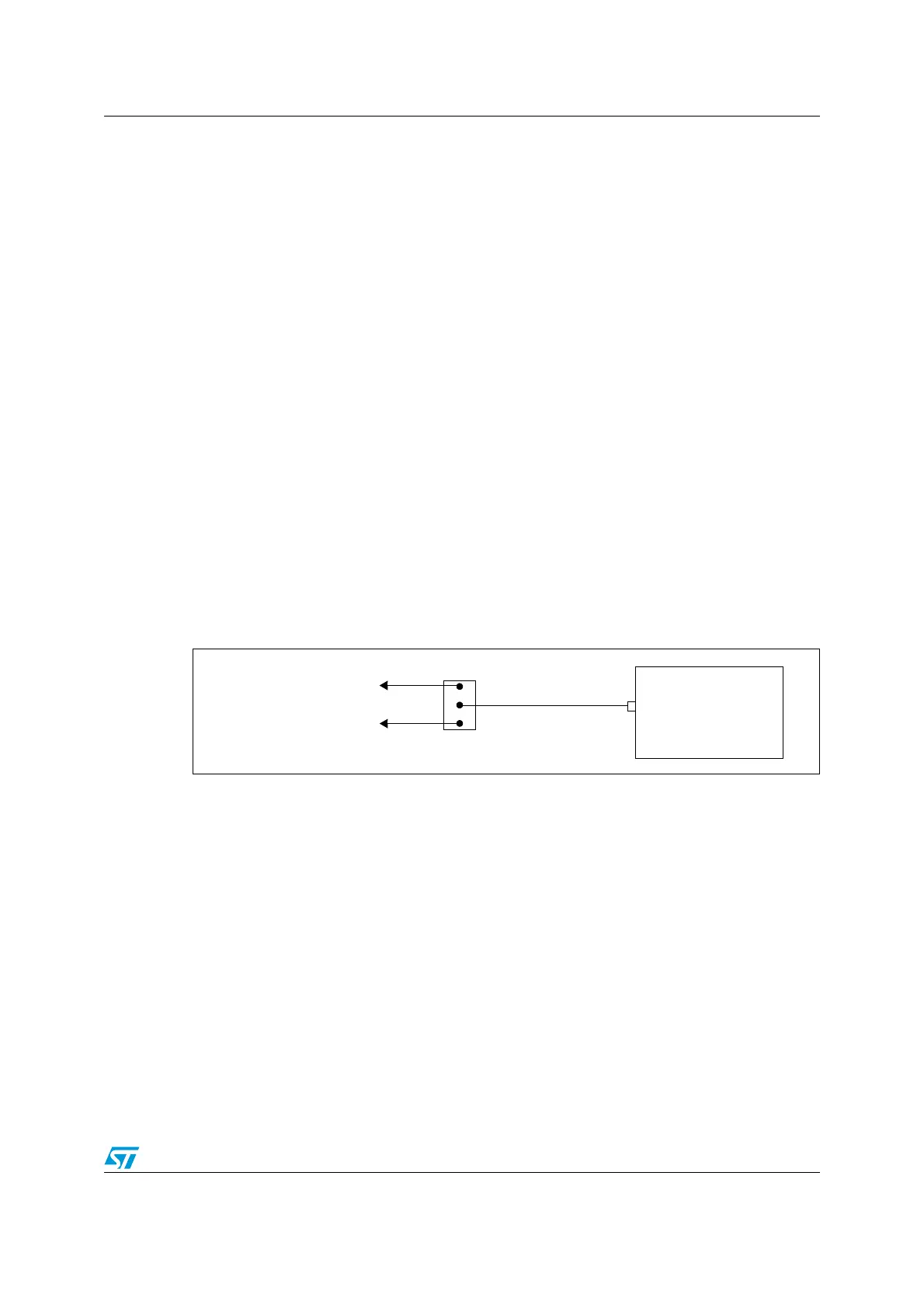
SWIM pin can be used as a standard I/O with some restrictions if you also want to use it for
debug. The most secure way is to provide on the PCB a strap option.
Figure 12. SWIM pin connection
5.3 SWIM modes
After a power-on reset, the SWIM is reset and enters OFF mode.
1. OFF: Default state after power-on reset. The SWIM pin cannot be used by the
application as an I/O.
2. I/O: This state is entered by software writing to the SWD bit in the Global configuration
register (CFG_GCR). In this state, the SWIM pin can be used by the application as a
standard I/O pin. In case of a reset, the SWIM goes back to OFF mode.
3. SWIM: This state is entered when a specific sequence is performed on the SWIM pin.
In this state, the SWIM pin is used by the host tool to control the STM8 with 3
commands (SRST system reset, ROTF read on the fly, WOTF write on the fly).
Note: Refer to the STM8 SWIM communication Protocol and Debug Module User Manual for a
description of the SWIM and Debug module (DM) registers.
MCU
SWIM/PA0
Jumper selection for
debug purposes
I/O for application
SWIM interface for tools

 Loading...


