RM0016 16-bit advanced control timer (TIM1)
Doc ID 14587 Rev 8 153/449
17.4.5 Trigger synchronization
There are four trigger inputs (refer to Table 35: Glossary of internal timer signals on
page 133):
● ETR
● TI1
● TI2
● TRGO from TIM5/TIM6
The TIM1 timer can be synchronized with an external trigger in three modes: Trigger
standard mode, trigger reset mode and trigger gated mode.
Trigger standard mode
The counter can start in response to an event on a selected input.
Procedure
Use the following procedure to start the up-counter in response, for example, to a rising
edge on the TI2 input:
1. Configure channel 2 to detect rising edges on TI2. As no filter is required in this
example, configure an input filter duration of 0 (IC2F = 0000). The capture prescaler is
not used for triggering and does not need to be configured. The CC2S bits select the
input capture source and do not need to be configured either. Write CC2P = 0 in the
TIM1_CCER1 register to select rising edge polarity.
2. Configure the timer in trigger mode by writing SMS = 110 in the TIM1_SMCR register.
Select TI2 as the input source by writing TS = 110 in the TIM1_SMCR register.
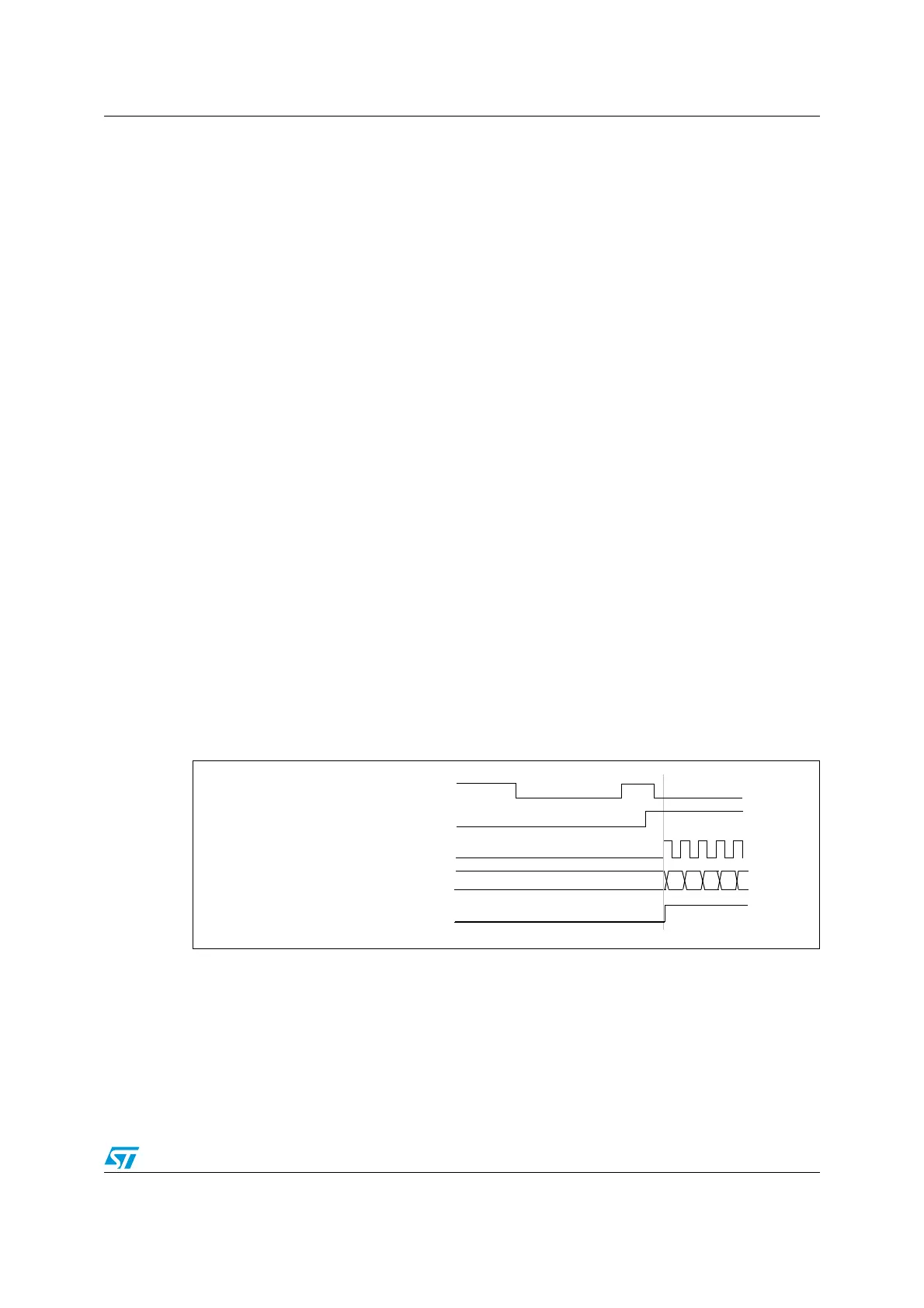
When a rising edge occurs on TI2, the counter starts counting on the internal clock and the
TIF flag is set.
The delay between the rising edge on TI2 and the actual reset of the counter is due to the
resynchronization circuit on TI2 input.
Figure 49. Control circuit in trigger mode
COUNTER CLOCK = CK_CNT = CK_PSC
COUNTER REGISTER
35 36 37 3834
TI2
CNT_EN
TIF

 Loading...


