Flash program memory and data EEPROM RM0016
40/449 Doc ID 14587 Rev 8
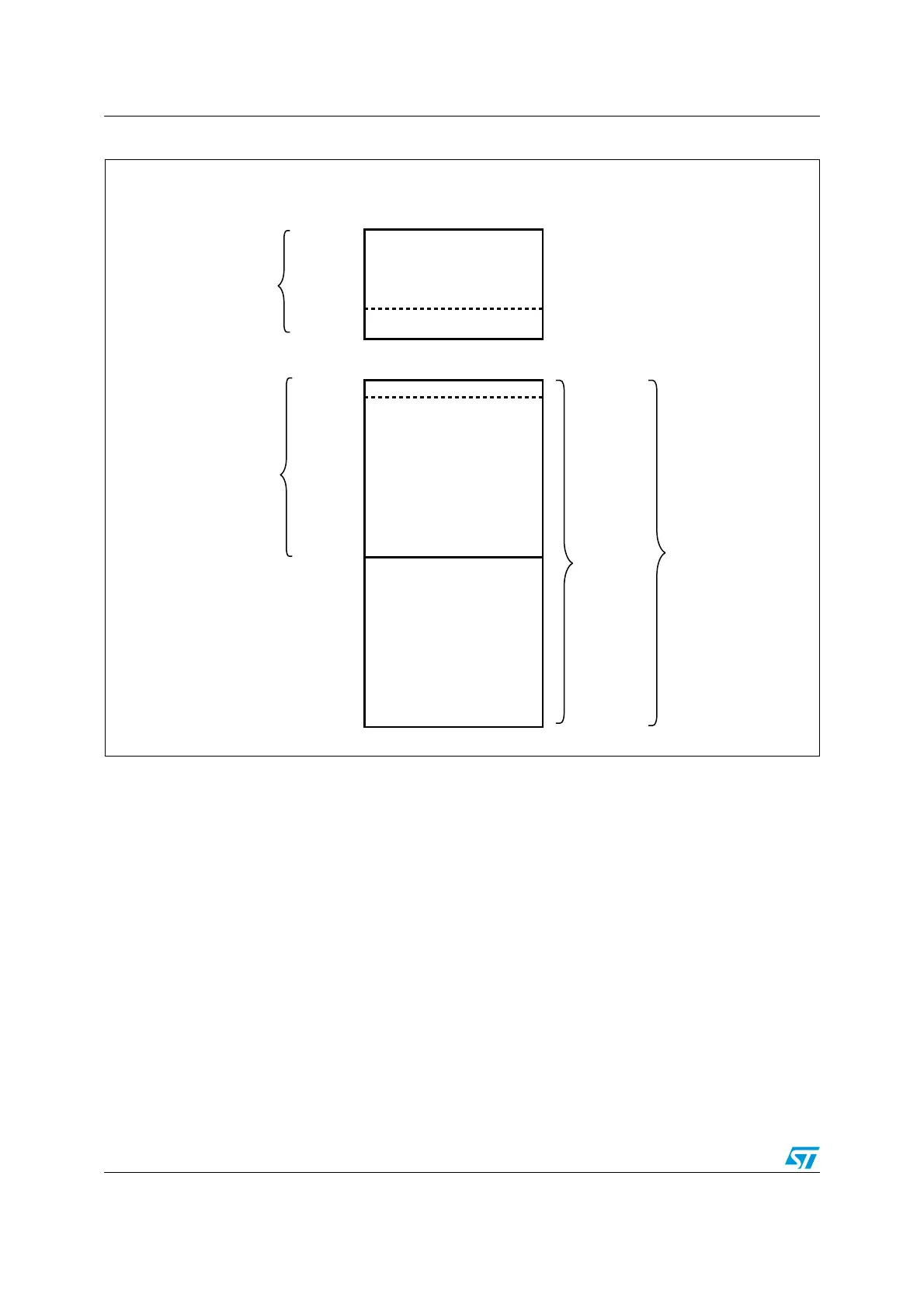
Figure 8. Flash memory and data EEPROM organization high density STM8S and STM8A
4.4.2 Memory access/ wait state configuration
The Flash/ data EEPROM access time allows the device to run at up to 16 MHz without wait
states.
When using the high-speed external clock (HSE) at higher frequencies up to 24 MHz, one
wait state is necessary. In this case the device option byte should be programmed to insert
this wait state. Refer to the datasheet option byte section.
4.4.3 User boot area (UBC)
The user boot area (UBC) contains the reset and the interrupt vectors. It can be used to
store the IAP and communication routines. The UBC area has a second level of protection
to prevent unintentional erasing or modification during IAP programming. This means that it
is always write protected and the write protection cannot be unlocked using the MASS keys.
The size of the UBC area can be obtained by reading the UBC option byte.
The size of the UBC area can be configured in ICP mode (using the SWIM interface)
through the UBC option byte. The UBC option byte specifies the number of pages allocated
for the UBC area starting from address 0x00 8000.
ai15501b
USER BOOT CODE (UBC)
(permanently write protected)
0x00 8000
MAIN PROGRAM
(write access possible for IAP
and using MASS mechanism)
0x02 7FFF
Programmable size
from 2 pages (1 Kbytes)
up to 64 or 128 Kbytes
(1 page steps)
DATA MEMORY
(up to 2 Kbytes)
32 to 128 Kbytes of
Flash Program
Memory
Flash program
memory
Interrupt vectors (128 bytes)
OPTION BYTES (1 block)
0x00 487F
0x00 4000
DATA EEPROM
1 page = 512 bytes
1 block = 128 bytes
0x00 47FF

 Loading...


