16-bit advanced control timer (TIM1) RM0016
146/449 Doc ID 14587 Rev 8
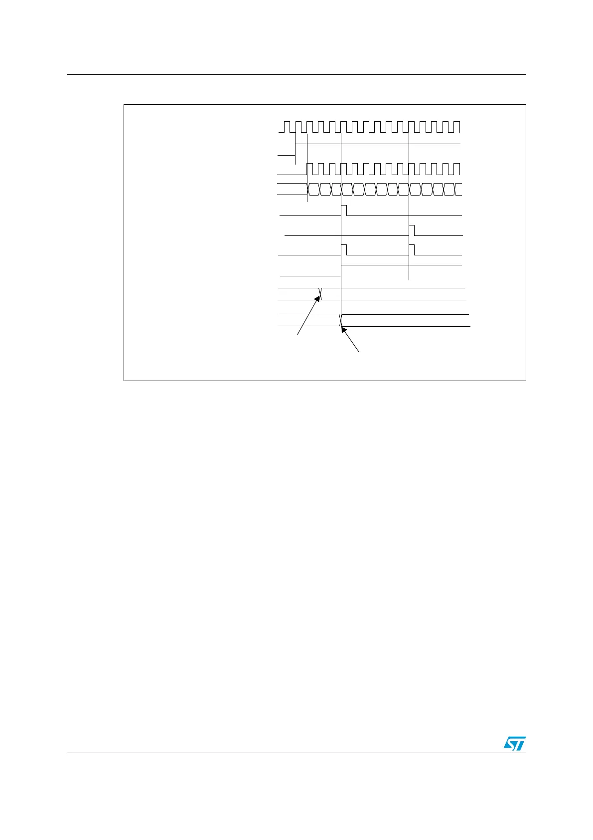
Figure 41. Counter timing diagram, f
CK_CNT
= f
CK_PSC
, TIM1_ARR = 06h, ARPE = 1
Hints on using center-aligned mode:
● When starting in center-aligned mode, the current up-down configuration is used. It
means that the counter starts counting up or down depending on the value written in
the DIR bit in the TIM1_CR1 register. Moreover, the DIR and CMS bits must not be
changed at the same time by the software.
● Writing to the counter while running in center-aligned mode is not recommended as it
can lead to unexpected results. In particular:
– The direction is not updated if a value is written in the counter that is greater than
the auto-reload value (TIM1_CNT>TIM1_ARR). For example, if the counter is
counting up, it continues to do so.
– The direction is updated if 0 or the TIM1_ARR value are written in the counter but
no UEV is generated.
● The safest way to use center-aligned mode is to generate an update by software
(setting the UG bit in the TIM1_EGR register) just before starting the counter. Avoid
writing to the counter while it is running.
CK_PSC
02
CNT_EN
TIMER CLOCK = CK_CNT
COUNTER REGISTER
UPDATE INTERRUPT FLAG (UIF)
COUNTER UNDERFLOW
UPDATE EVENT (UEV)
03 04 05 06 05 04 0303 02 01 00 0104
COUNTER OVERFLOW
AUTO-RELOAD PRELOAD REGISTER
FD 06
AUTO-RELOAD SHADOW REGISTER
FD 06
Write a new value in TIMx_ARR
New value transferred in shadow register
on update event

 Loading...


