Universal asynchronous receiver transmitter (UART) RM0016
350/449 Doc ID 14587 Rev 8
22.7.2 Data register (UART_DR)
Address offset: 0x01
Reset value: 0xXX
22.7.3 Baud rate register 1 (UART_BRR1)
The Baud Rate Registers are common to both the transmitter and the receiver. The baud
rate is programmed using two registers BRR1 and BRR2. Writing of BRR2 (if required)
should precede BRR1, since a write to BRR1 will update the baud counters.
See Figure 118: How to code UART_DIV in the BRR registers on page 321 and Table 54:
Baud rate programming and error calculation on page 322
Note: 1 The baud counters stop counting if the TEN or REN bits are disabled respectively.
Address offset: 0x02
Reset value: 0x00
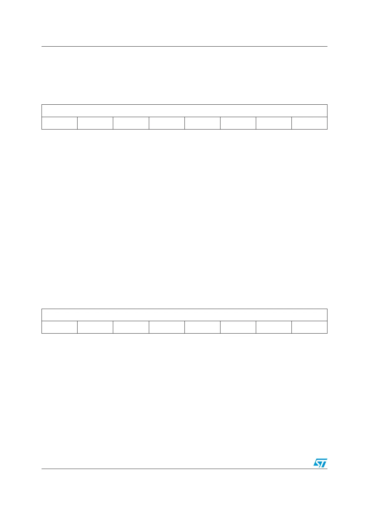
76543210
DR[7:0]
rw rw rw rw rw rw rw rw
Bits 7:0 DR[7:0]: Data value
Contains the Received or Transmitted data character, depending on whether it is read from or
written to.
The Data register performs a double function (read and write) since it is composed of two registers,
one for transmission (TDR) and one for reception (RDR)
The TDR register provides the parallel interface between the internal bus and the output shift
register.
The RDR register provides the parallel interface between the input shift register and the internal bus.
76543210
UART_DIV[11:4]
rw rw rw rw - rw rw rw
Bits 7:0 UART_DIV[11:4] UART_DIV bits
(1)
These 8 bits define the 2nd and 3rd nibbles of the 16-bit UART divider (UART_DIV).
1. BRR1 = 00h means UART clock is disabled.
 Loading...


