General purpose I/O ports (GPIO) RM0016
108/449 Doc ID 14587 Rev 8
11.4 Reset configuration
All I/O pins are generally input floating under reset (i.e. during the reset phase) and at reset
state (i.e. after reset release). However, a few pins may have a different behavior. Refer to
the datasheet pinout description for all details.
11.5 Unused I/O pins
Unused I/O pins must be connected to fixed voltage levels and configured as input floating.
Either connect a pull-up or pull-down to the unused I/O pins, or use the internal weak pull-up
if it is available on the pins.
11.6 Low power modes
Note: If PA1/PA2 pins are used to connect an external oscillator, to ensure a lowest power
consumption in Halt mode, PA1 and PA2 must be configured as input pull-up.
11.7 Input mode details
11.7.1 Alternate function input
Some I/Os can be used as alternate function input. For example as the port may be used as
the input capture input to a timer. Alternate function inputs are not selected automatically,
you select them by writing to a control bit in the registers of the corresponding peripheral.
For Alternate Function input, you should select floating or pull-up input configuration in the
DDR and CR1 registers.
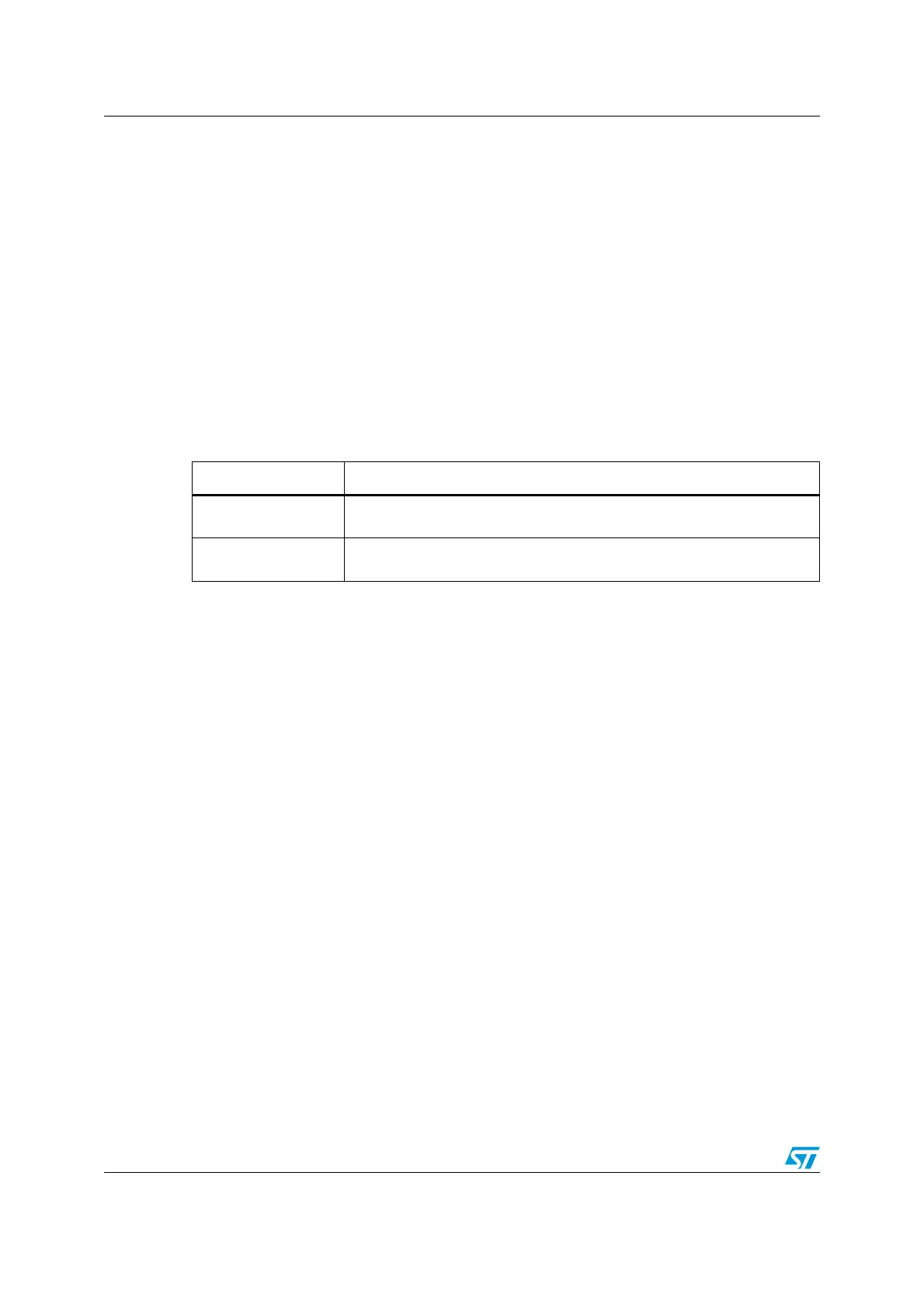
Table 22. Effect of low power modes on GPIO ports
Mode Description
Wait
No effect on I/O ports. External interrupts cause the device to exit from Wait
mode.
Halt
No effect on I/O ports. External interrupts cause the device to wakeup from
Halt mode.

 Loading...


