RM0016 Universal asynchronous receiver transmitter (UART)
Doc ID 14587 Rev 8 315/449
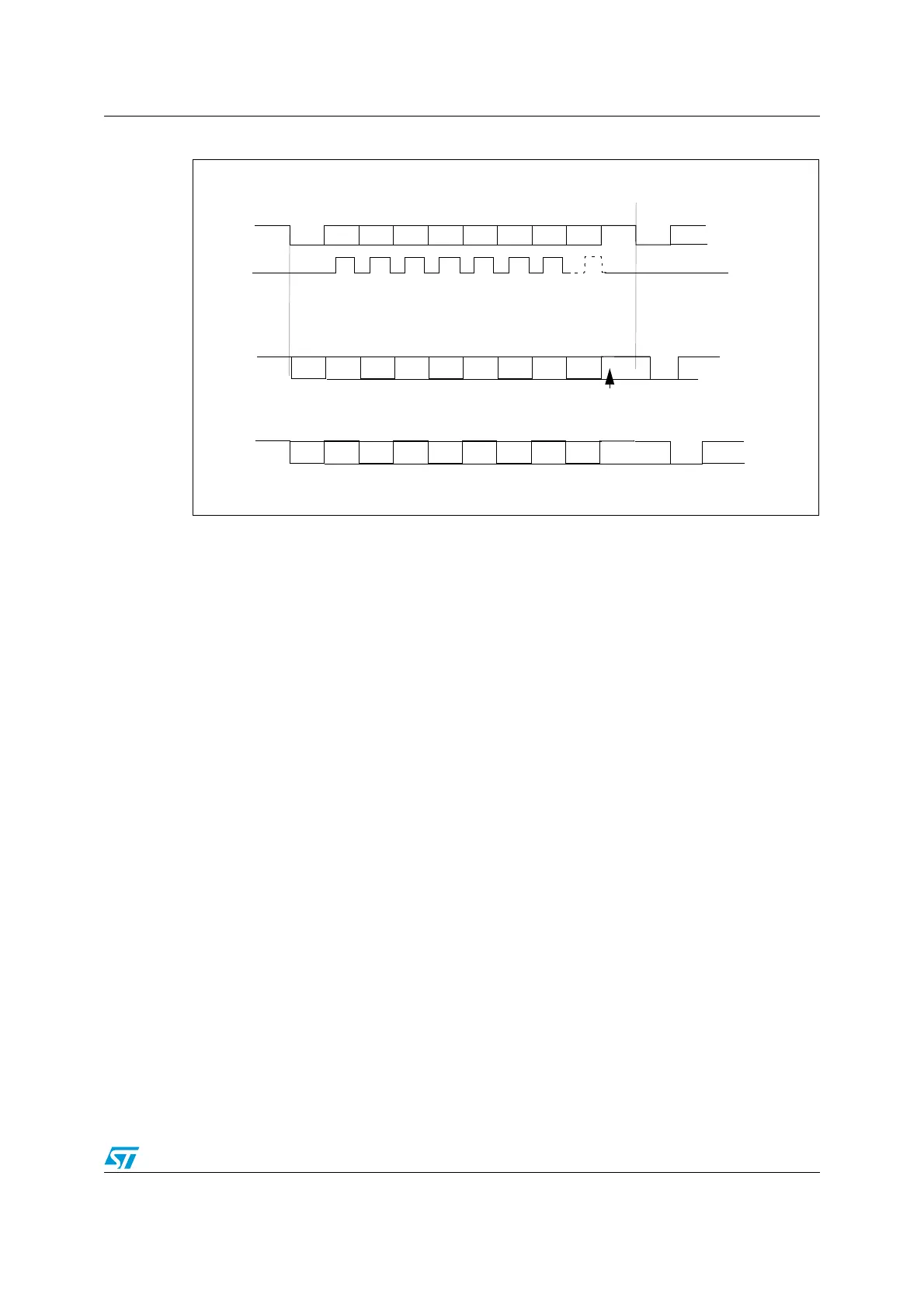
Figure 114. Configurable stop bits
Procedure:
1. Program the M bit in UART_CR1 to define the word length.
2. Program the number of stop bits in UART_CR3.
3. Select the desired baud rate by programming the baud rate registers in the following
order:
a) UART_BRR2
b) UART_BRR1
4. Set the TEN bit in UART_CR2 to enable transmitter mode.
5. Write the data to send in the UART_DR register (this clears the TXE bit). Repeat this
for each data to be transmitted in case of single buffer.
6. Once the last data is written to the UART_DR register, wait until TC is set to ‘1’, which
indicates that the last data transmission is complete. This last step is required, for
instance, to avoid last data transmission corruption when disabling the UART or
entering Halt mode.
Bit0
Bit1
Bit2
Bit3
Bit4
Bit5 Bit6
Bit7
Start
Bit
Stop
Bit
Next
Start
Bit
8-bit Word length (M bit is reset)
Possible
Parity
Bit
Data Frame
Next Data Frame
****
** LBCL bit controls last data clock pulse
CLOCK
**
Bit0
Bit1
Bit2
Bit3
Bit4
Bit5
Bit6
Bit7
Start
Bit
2 Stop
Bits
Next
Start
Bit
Possible
Parity
Bit
Data Frame
Next Data Frame
Bit0
Bit1
Bit2
Bit3
Bit4
Bit5
Bit6
Bit7
Start
Bit
Next
Start
Bit
Possible
Parity
Bit
Data Frame
Next Data Frame
1 1/2 stop bits
a) 1 Stop Bit
b) 1 1/2 stop Bits *
c) 2 Stop Bits

 Loading...


