RM0016 16-bit advanced control timer (TIM1)
Doc ID 14587 Rev 8 155/449
Trigger gated mode
The counter can be enabled depending on the level of a selected input.
Example
Use the following procedure to enable the up-counter when TI1 input is low:
1. Configure channel 1 to detect low levels on TI1. Configure the input filter duration (IC1F
= 0000). The capture prescaler is not used for triggering and does not need to be
configured. The CC1S bits select the input capture source and do not need to be
configured either. Write CC1P = 1 in the TIM1_CCER1 register to validate the polarity
(and detect low level).
2. Configure the timer in trigger gated mode by writing SMS = 101 in the TIM1_SMCR
register. Select TI1 as the input source by writing TS = 101 in the TIM1_SMCR register.
3. Enable the counter by writing CEN = 1 in the TIM1_CR1 register (in trigger gated
mode, the counter does not start if CEN = 0 irrespective of the trigger input level).
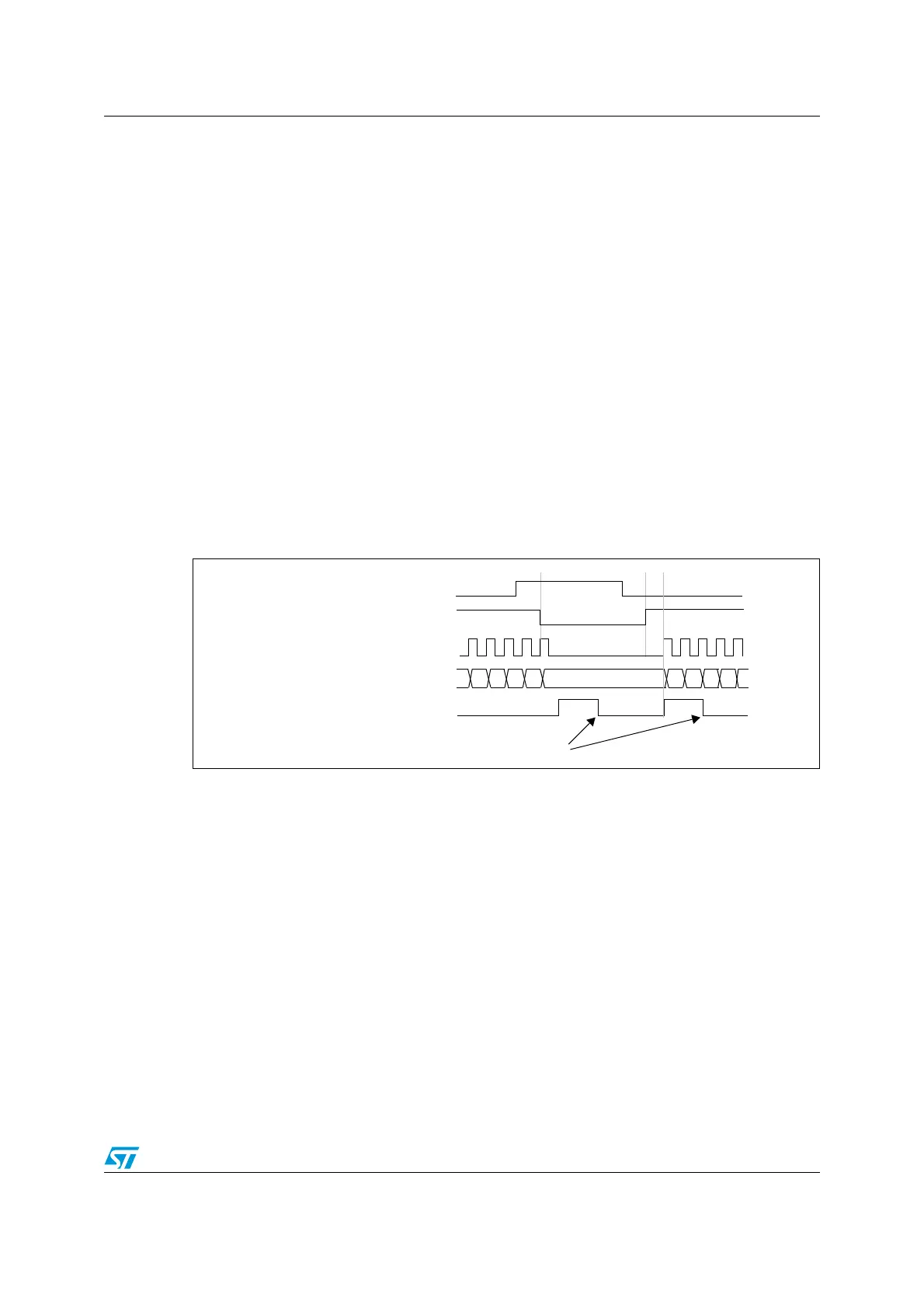
The counter starts counting on the internal clock as long as TI1 is low. It stops as soon as
TI1 becomes high. The TIF flag is set when the counter starts or stops.
The delay between the rising edge on TI1 and the actual reset of the counter is due to the
resynchronization circuit on TI1 input.
Figure 51. Control circuit in trigger gated mode
COUNTER CLOCK = CK_CNT = CK_PSC
COUNTER REGISTER
35 36 37 3832 33 34
TI1
3130
CNT_EN
TIF
Write TIF=0

 Loading...


