16-bit advanced control timer (TIM1) RM0016
160/449 Doc ID 14587 Rev 8
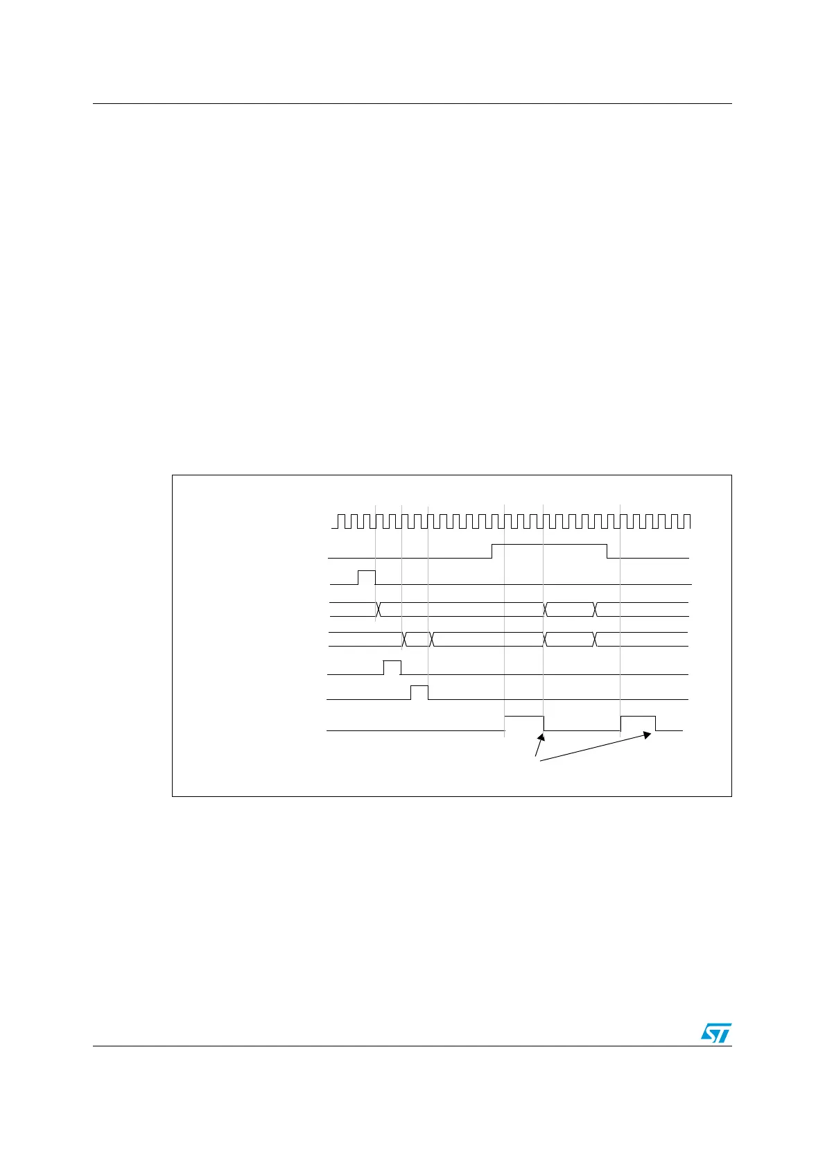
Example 2
Timer A and timer B are synchronized. Timer A is the master and starts from 0. Timer B is
the slave and starts from E7h. The prescaler ratio is the same for both timers. Timer B stops
when timer A is disabled by writing 0 to the CEN bit in the TIMx_CR1 register:
1. Configure timer A master mode to send its output compare 1 reference (OC1REF)
signal as trigger output (MMS = 100 in the TIMx_CR2 register).
2. Configure the timer A OC1REF waveform (TIMx_CCMR1 register)
3. Configure timer B to get the input trigger from timer A (TS = 001 in the TIMx_SMCR
register).
4. Configure timer B in trigger gated mode (SMS = 101 in TIMx_SMCR register)
5. Reset timer A by writing 1 in UG bit (TIMx_EGR register)
6. Reset timer B by writing 1 in UG bit (TIMx_EGR register)
7. Initialize timer B to 0xE7 by writing ‘E7h’ in the timer B counter (TIMx_CNTRL)
8. Enable timer B by writing 1 in the CEN bit (TIMx_CR1 register)
9. Start timer A by writing 1 in the CEN bit (TIMx_CR1 register)
10. Stop timer A by writing 0 in the CEN bit (TIMx_CR1 register)
Figure 57. Gating timer B with the counter enable signal of timer A (CNT_EN)
Timer B-TIF
Write TIF=0
75 00 01
f
MASTER
Timer A-CEN = CNT_EN
Timer A-CNT
Timer B-CNT
02
Timer A-UG
AB 00
E7
E8 E9
Timer B-UG
Timer B
write CNT

 Loading...


