RM0016 Flash program memory and data EEPROM
Doc ID 14587 Rev 8 43/449
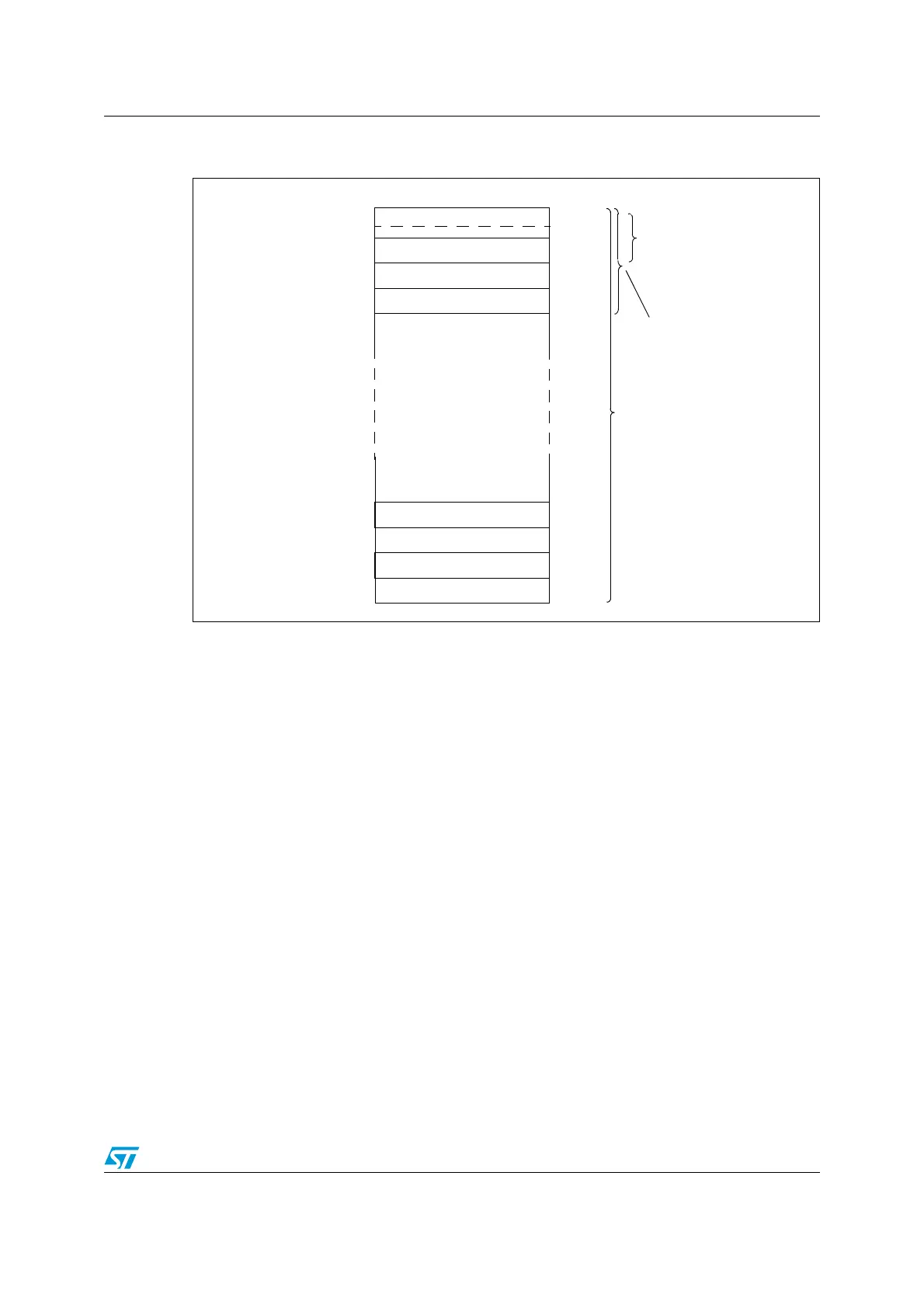
Figure 11. UBC area size definition on high density STM8S and
STM8A with up to 128 Kbytes of Flash program memory
1. UBC[7:0] = 0x00 means no user boot code area is defined. Refer to the datasheets for the description of
the UBC option byte.
2. The first 2 pages (1 Kbytes) contain the interrupt vectors, of which only 128 bytes (32 IT vectors) are used.
4.4.4 Data EEPROM (DATA)
The data EEPROM area can be used to store application data. By default, the DATA area is
write protected to prevent unintentional modification when the main program is updated in
IAP mode. The write protection can be unlocked only by using a specific MASS key
sequence (refer to Enabling write access to the DATA area).
Refer to Section 4.4: Memory organization for the size of the DATA area.
4.4.5 Main program area
The main program is the part of the Flash program memory which is used to store the
application code (see Figure 6, Figure 7 and Figure 8).
4.4.6 Option bytes
The option bytes are used to configure device hardware features and memory protection.
They are located in a dedicated memory array of one block.
The option bytes can be modified both in ICP/SWIM and in IAP mode, with OPT bit of the
FLASH_CR2 register set to 1 and the NOPT bit of the FLASH_NCR2 register set to 0 (see
Section 4.8.2: Flash control register 2 (FLASH_CR2) and Section 4.8.3: Flash
complementary control register 2 (FLASH_NCR2)).
0x02 7FFF
0x02 7E00
0x02 7C00
0x02 7A00
0x02 7800
0x00 8800
0x00 8600
0x00 8400
0x00 8200
Page 255
Page 254
Page 253
Page 252
Page 3
Page 2
Page 1
Page 0
0x00 8000
UBC[7:0] =0x01
512 bytes
512 bytes
512 bytes
512 bytes
512 bytes
512 bytes
512 bytes
1K to 128 Kbytes
1 Kbytes
UBC[7:0] =0xFE
128 Kbytes
User boot code area
UBC[7:0] =0x02
2 Kbytes
0x00 807F
Interrupt vector table

 Loading...


