16-bit advanced control timer (TIM1) RM0016
156/449 Doc ID 14587 Rev 8
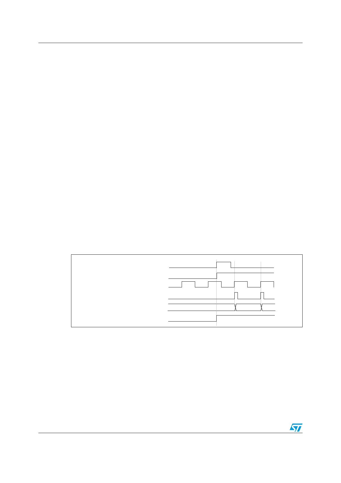
Combining trigger modes with external clock mode 2
External clock mode 2 can be used with another trigger mode. For example, the ETR can be
used as the external clock input, and a different input can be selected as trigger input (in
trigger standard mode, trigger reset mode, or trigger gated mode). Care must be taken not
to select ETR as TRGI (through the TS bits in the TIM1_SMCR register).
Example
Use the following procedure to enable the up-counter at each rising edge on the ETR as
soon as a rising edge occurs on TI1 (standard trigger mode with external ETR clock):
1. Configure the external trigger input circuit by writing to the TIM1_ETR register. Write
ETF = 0000 (no filter needed in this example). Write ETPS = 00 to disable the
prescaler, write ETP = 0 to detect rising edges on the ETR, and write ECE = 1 to
enable external clock mode 2.
2. Configure channel 1 to detect rising edges on TI1. Configure the input filter duration
(IC1F = 0000). The capture prescaler is not used for triggering and does not need to be
configured. The CC1S bits select the input capture source and do not need to be
configured either. Write CC1P = 0 in the TIM1_CCER1 register to select rising edge
polarity.
3. Configure the timer in trigger mode by writing SMS = 110 in the TIM1_SMCR register.
Select TI1 as the input source by writing TS = 101 in the TIM1SMCR register.
A rising edge on TI1 enables the counter and sets the TIF flag. Consequently, the counter
counts on the ETR rising edges.
The delay between the rising edge on TI1 and the actual reset of the counter is due to the
resynchronization circuit on TI1 input. The delay between the rising edge on the ETR and
the actual reset of the counter is due to the resynchronization circuit on the ETRP signal.
Figure 52. Control circuit in external clock mode 2 + trigger mode
COUNTER CLOCK = CK_CNT = CK_PSC
COUNTER REGISTER
35 3634
ETR
CEN
TIF
TI1

 Loading...


