16-bit advanced control timer (TIM1) RM0016
182/449 Doc ID 14587 Rev 8
17.5.10 Encoder interface mode
Encoder interface mode is typically used for motor control. It can be selected by writing:
● SMS = 001 in the TIM1_SMCR register if the counter is counting on TI2 edges only
● SMS = 010 if the counter is counting on TI1 edges only
● SMS = 011 if the counter is counting on both TI1 and TI2 edges
Select the TI1 and TI2 polarity by programming the CC1P and CC2P bits in the
TIM1_CCER1 register. When needed, the input filter can also be programmed.
The two inputs TI1 and TI2 are used to interface an incremental encoder (see Table 37). If
the counter is enabled (when the CEN bit in the TIM1_CR1 register is written to 1), it is
clocked by each valid transition on TI1FP1 or TI2FP2 (see Figure 64: Input stage of TIM 1
channel 1). The transition sequences of the two inputs (TI1 and TI2) are evaluated and
generate count pulses and a direction signal. Depending on the sequence, the counter
counts up or down, and the DIR bit in the TIM1_CR1 register is modified accordingly by
hardware. The DIR bit is calculated at each transition based on inputs from either TI1 or TI2.
without this being dependent on whether the counter is counting pulses on TI1, TI2 or both.
Encoder interface mode acts as an external clock with direction selection. The counter
counts continuously between 0 and the auto-reload value in the TIM1_ARR register (0 to
ARR or ARR down to 0 depending on the direction). TIM1_ARR must be configured before
starting. The capture, compare, prescaler, and trigger output features continue to work as
normal in this mode. Encoder mode and external clock mode 2 are not compatible and must
not be selected together.
In encoder interface mode, the counter is modified automatically depending on the speed
and the direction of the incremental encoder. The content of the counter therefore always
represents the encoder's position. The count direction corresponds to the rotation direction
of the connected sensor. Tab le 3 7 summarizes the possible combinations of counting
directions and encoder signals, assuming that TI1 and TI2 do not switch at the same time.
An external incremental encoder can be connected directly to the MCU without external
interface logic. However, comparators are normally used to convert the encoder’s differential
outputs to digital signals. This greatly increases noise immunity. The third encoder output
which indicates the mechanical zero position, may be connected to an external interrupt
input and trigger a counter reset.
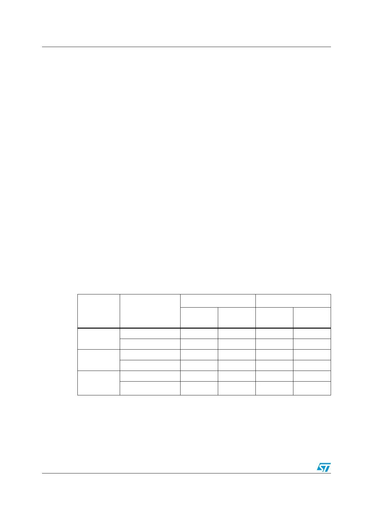
Table 37. Counting direction versus encoder signals
Active edge
Level on opposite
signal
(TI1FP1 for TI2,
TI2FP2 for TI1)
TI1FP1 signal TI2FP2 signal
Rising Falling Rising Falling
Counting on
TI1 only
High Down Up No count No count
Low Up Down No count No count
Counting on
TI2 only
High No count No count Up Down
Low No count No count Down Up
Counting on
both TI1 and
TI2
High Down Up Up Down
Low Up Down Down Up

 Loading...


