RM0016 Flash program memory and data EEPROM
Doc ID 14587 Rev 8 41/449
Refer to Figure 9, Figure 10, and Figure 11 for a description of the UBC area memory
mapping and to the option byte section in the datasheets for more details on the UBC option
byte.
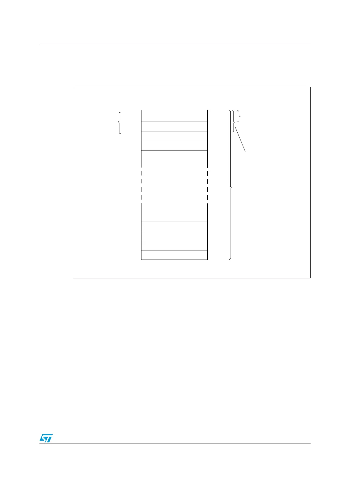
Figure 9. UBC area size definition on low density STM8S devices
1. N (number of protected pages) = UBC[7:0].
2. UBC[7:0] = 0x00 means no user boot code area is defined. Refer to the datasheets for the description of
the UBC option byte.
3. The first 2 pages (128 bytes) contain the interrupt vectors.
0x00 9FFF
0x00 9FC0
0x00 9F80
0x00 9F40
0x00 9F00
0x00 8100
0x00 8080
0x00 8040
Page 127
Page 126
Page 125
Page 124
Page 3
Page 2
Page 1
Page 0
0x00 8000
UBC[7:0] =0x01
64 bytes
64 bytes
64 bytes
64 bytes
64 bytes
64 bytes to 8 Kbytes
64 bytes
user boot code area
UBC[7:0] =0x02
128 bytes
64 bytes
0x00 80C0
64 bytes
64 bytes
Interrupt vectors
UBC[7:0] =0x7F
8 Kbytes

 Loading...


