RM0016 Inter-integrated circuit (I
2
C) interface
Doc ID 14587 Rev 8 289/449
S= Start, S
r
= Repeated Start, P= Stop, A= Acknowledge, NA= Non-acknowledge,
EVx= Event (with interrupt if ITEVTEN=1).
EV5: SB=1, cleared by reading SR1 register followed by writing the DR register.
EV6: ADDR1, cleared by reading SR1 register followed by reading SR3.
In 10-bit master receiver mode, this sequence should be followed by writing CR2 with START = 1.
EV6_1: No associated flag event. The acknowledge should be disabled just after EV6, that is after ADDR is
cleared
EV7_3: BTF = 1, program STOP = 1, read DR twice (Read Data1 and Data2) just after programming the
STOP.
EV9: ADD10= 1, cleared by reading SR1 register followed by writing DR register.
2. EV5, EV6 and EV9 events stretch SCL low until the end of the corresponding software sequence.
3. EV6_1 software sequence must be completed before the ACK pulse of the current byte transfer.
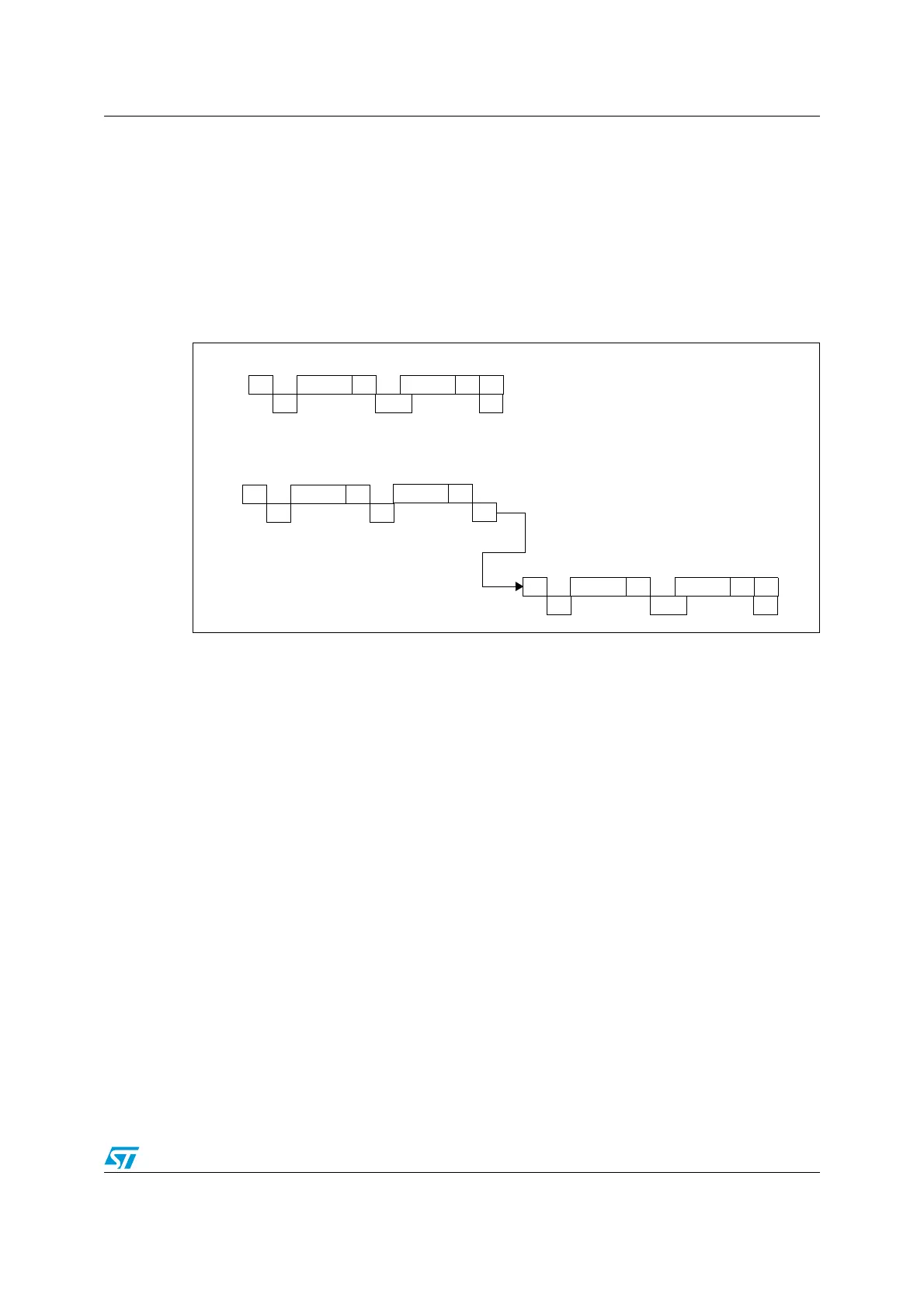
Figure 108. Method 2: transfer sequence diagram for master receiver when N=1
1. Legend:
S= Start, S
r
= Repeated Start, P= Stop, A= Acknowledge, NA= Non-acknowledge,
EVx= Event (with interrupt if ITEVTEN=1).
EV5: SB=1, cleared by reading SR1 register followed by writing the DR register.
EV6: ADDR =1, cleared by reading SR1 resister followed by reading SR3 register.
EV6_3: ADDR = 1, program ACK = 0, clear ADDR by reading SR1 register followed by reading SR3
register, program STOP =1 just after ADDR is cleared.
EV7: RxNE =1, cleared by reading DR register.
EV9: ADD10= 1, cleared by reading SR1 register followed by writing DR register.
2. EV5, EV6 and EV9 events stretch SCL low until the end of the corresponding software sequence.
3. EV6_3 software sequence must be completed before the ACK pulse of the current byte transfer.
21.4.3 Error conditions
The following are the error conditions which may cause communication to fail.
AAddressS
EV5
NAData1
EV7
P
EV6_3
10- bit master receiver
AHeaderS
EV5 EV9
AAddress
EV6
7- bit master receiver
NAData1
EV7
P
EV6_3
AHeaderS
r
EV5

 Loading...


