RM0016 16-bit advanced control timer (TIM1)
Doc ID 14587 Rev 8 165/449
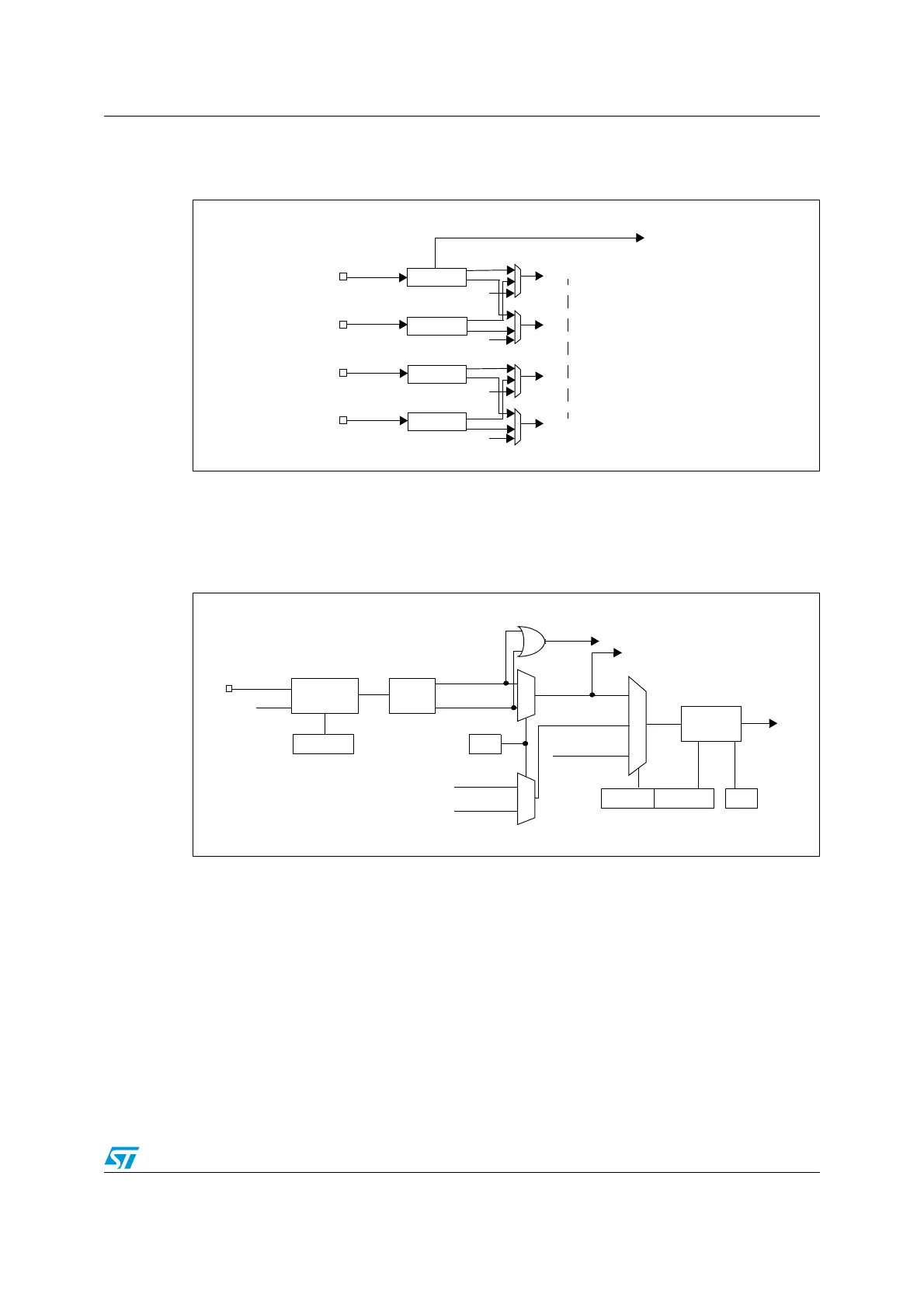
17.5.2 Input stage
Figure 63. Channel input stage block diagram
Figure 64 shows how the input stage samples the corresponding TIi input to generate a
filtered signal TIiF. Then, an edge detector with polarity selection, generates a signal
(TIiFPn) which can be used as trigger input by the clock/trigger controller or as the capture
command. The signal is prescaled before entering the capture register (ICiPS).
Figure 64. Input stage of TIM 1 channel 1
IC1
IC2
Input Filter &
EdgeDetector
TI1FP1
TRC
TRC
IC3
Input Filter &
EdgeDetector
Input Filter &
EdgeDetector
TI1FP2
TI2FP1
TI2FP2
TI3
TI1
TI2
TIM1_CH1
TIM1_CH2
TIM1_CH3
IC4
Input Filter &
EdgeDetector
TI4
TIM1_CH4
TI3FP3
TRC
TRC
TI3FP4
TI4FP3
TI4FP4
to clock/trigger controller
TRC
TI1F_ED
to capture/compare channels
TI1
0
1
TIMx_CCER1
CC1P
divider
/1, /2, /4, /8
ICPS[1:0]
TI1F_ED
filter
ICF[3:0]
down-counter
TIMx_CCMR1
Edge
detector
TI1F_rising
TI1F_falling
to clock/trigger controller
TI1FP1
11
01
TIMx_CCMR1
CC1S[1:0]
IC1
TI2FP1
TRC
(from channel 2)
(from clock/trigger
controller)
10
f
MASTER
TIMx_CCER1
CC1E
ICPS
TI1F
0
1
TI2F_rising
TI2F_falling
(from channel 2)

 Loading...


